
A number of people asked for more details on building meter shunts thus, this article.Underlined colored text blocks are hyperlinks that you may click on for more information on the topic discussed.
To complete the "Glowbug Project", I decided to build a fully self-contained, re-chargeable battery pack to enable operation of the rig in a portable environment. This meter is part of that project.
The meter is a dual voltage dual current meter, switchable to monitor the High Voltage or "A" supply, and the Filament or "B" supply. The current portion of the meter required a shunt of appropriate values for the currents anticipated both during normal discharge operation, and charging current.
|
|
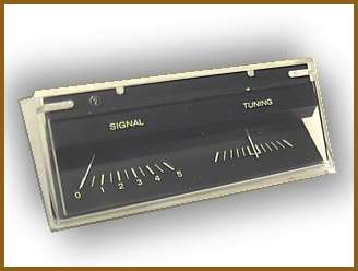
| This is a picture of the original meter, purchased from All Electronics, Meter # MET-49. It is a dual meter orignally intended to be used as a Hi-Fi Stereo reception meter, indicating signal strength and center of station tuning. | This is a picture of the meter after modification for this specific purpose. The Signal strength meter was modified to show voltage, and the center tune meter modified to indicate charge and discharge current. |
Notice the modified meter has two scales to indicate currents and voltages for the "A" and "B" supplies. The appropriate shunt values are switched in according to the need. To determine the values of these shunts, it is first necessary to find the internal resistance of the meter.
If you know the full scale deflection current rating of the meter AND have a variable low voltage power supply, this can be done very easily. Simply connect the meter to the power supply and VERY slowly so as to avoid pinning the meter against it's peg, turn up the supply to bring the meter to the full scale reading. In this case, .1 volt caused a full scale meter deflection. Although the power supply has a built in voltage meter I never trust these readings when highly accurate measurements are necessary. Instead, use the highest quality DMM you have available.
In this case the meter is rated at 250ua full scale. Employing ohms law we discover the internal resistance to be .1/.00025 = 400 ohms. This is a very convenient as to obtain the shunt value needed, it is only necessary to divide this resistance value by the same multiplier used for the ultimate meter requirements. For example, we need a meter that will read 100ma full scale. That's 400 times the stock 250 microampere rating of the meter. 400 ohms / 400 = 1 ohm. The shunt value will be 1 ohm.
For high current readings, We need a 500ma fullscale reading. 500ma is 2000 times 250ua thus 400 ohms / 2000 = .2 ohms. Simple, eh? These values are convenient as they are available as common resistors. I suggest using 1% tolerance resitors and in addition, make measurements with this resistor to mark your new meter face accordingly. When complete use the exact same resistor in the final application to avoid tolerance errors. Also, use ohms law again to calculate the power dissipation anticipated and use the appropriate wattage resistor.
In many other cases it may be necessary to use a extremely low value of resistance not commonly available as a resistor. In these cases it is necessary to calulate the resistance of a specific guage wire, cut a piece to the calculated length, wind the wire into a coil and mount it across the meter teminals.These quantities can be found in the ARRL handbook and other data book sources.
 |
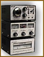 |
| This is a picture of the completed Rechargeable Battery Power Supply Click here for more information on this project. | This is the completed Glowbug Project. Click Here for more information. |