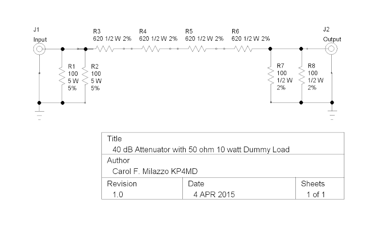
Figure 1. Schematic Diagram
|
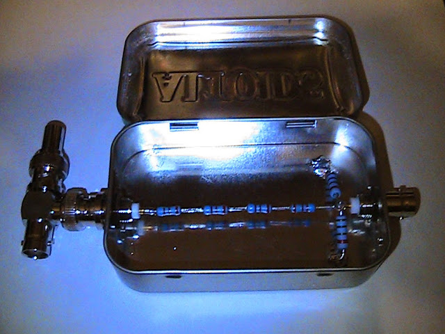
Figure 2. 1/2 watt 50 ohm termination and 40
dB attenuator. |

Figure 3. 10 watt 50 ohm load and 40 dB
attenuator.
Two five watt 100 ohm metal oxide film resistors
in parallel
across the attenuator input. This physical layout
minimized the
inductive reactance on the input measured up to
200 MHz. |

Figure 4. VNA measuring SWR & Impedance
|

Figure 5. Vector Network Analyzer measuring
Attenuation
|
INTRODUCTION
This 50 ohm impedance terminator & attenuator
(dummy load) provides a non-reactive load (VSWR
<1.03:1 from 0-200 MHz) and 40 dB attenuation for
frequency and power measurements of radio frequency
sources up to 10 watts (40 dBm). This provides the
appropriate signal level for low level measurement
devices such as a frequency meter,
oscilloscope or spectrum analyzer. The
attenuator is constructed with low cost available
components and fits conveniently inside an Altoids tin
box.
DESIGN AND CONSTRUCTION
Parts list:
- J1, J2 - Two single hole chassis mount BNC female
connectors,
- R1, R2 - Two 100
ohm 5% 5 watt metal oxide film resistors,
- R3-R6 - Four 620 ohm 2% � watt metal film resistors,
- R7, R8 - Two 100 ohm 2% � watt metal film resistors,
- All resistors should be non-inductive (not
wirewound), thermally stable (not carbon composition)
and of appropriate power rating,
- and an Altoids tin.
The 40 dB Attenuator Circuit. The 40 dB
attenuator (shown in Figure 1 excluding R1 and R2)
consists of a 100:1 voltage divider comprised of 2480
ohms (R3 through R6) in series with 50 ohms (R7 and R8
in parallel). When the 50 ohm input impedance of the
measuring device is attached to output jack J2 in
parallel across R7 and R8, the output resistance becomes
25 ohms, that is ~1/100 of total 2505 ohm resistance
that is presented to the input signal at J1. The
100-fold voltage attenuation yields a 104-fold
or 40 dB power attenuation at the output jack J2.
A full 10 watts (40 dBm) applied to a 50 ohm load at
input jack J1 will produce 22.4 volts across and ~9 mA
through the voltage divider (each 620 ohm resistor will
dissipate about 0.05 watts, well within its 0.5 watt
maximum rating), and the voltage at output jack J2 will
be 224 mV, equivalent to 1 mW (0 dBm).
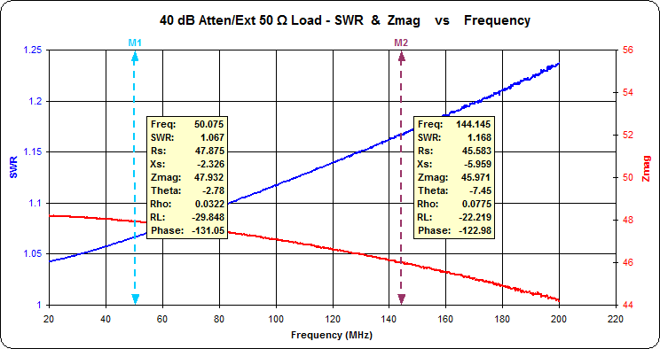
First configuration: External 1/2 watt 50 ohm
Terminator on BNC Tee Connector with 40 dB Attenuator
(Figure 2). The 50 ohm � watt termination
shown attached to the BNC tee connector in Figure 2
provides the proper impedance load for a signal source
up to 0.5 watt (27 dBm) applied to the input jack. The
internal lead length and stray capacitance of the BNC
Tee connector are expected to introduce a reactive load
at higher frequencies. With the 50 ohm termination
removed, the BNC tee connector may be left connected in
line between
a transmitter and a 50 ohm antenna for on the air power
and frequency measurements. Power measurements
taken in this manner will be accurate only when the
antenna presents a non-reactive 50 ohm load.
Second configuration: Internal 10 watt 50 ohm
Terminator with 40 dB Attenuator (Figure 3).
The BNC tee connector and 50 ohm termination were
removed from input jack J1 and the 10 watt 50 ohm
internal load consisting of two 100 ohm 5 watt metal
oxide film resistors (R1 and R2) were soldered in
parallel from the input jack J1 to ground. This
configuration serves for accurate measurement of
transmitter power up to 10 watts (40 dBm) into the
internal non-reactive 50 ohm load but does not permit
inline measurements between the transmitter and an
antenna.
PARAMETER EVALUATION
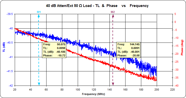
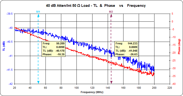
For comparison of both configurations, the input
impedance and attenuation parameters of each were
evaluated over 1-200 MHz using a miniVNA Pro vector
network analyzer2 (Figures 4 through 13) and
the observed values for 1.9, 28, 50 and 144 MHz were
charted in Table 1.
For either configuration, the attenuation varied
between 40 dB and 40.2 dB up to 50 MHz, and approached
41.5 dB at 200 MHz. The internal 10 watt 50 ohm
load presented the least reactance with an SWR from
1.015:1 to 1.025:1 between 0.1 and 200 MHz, while the
attenuator with the external 50 ohm termination and BNC
tee connector presented a higher input SWR from 1.04:1
to 1.17:1 over that range.
Table 1. 50 ohm Terminator with 40 dB Attenuator
Characteristics
CONCLUSION
This 10 watt 50 ohm load with 40 dB attenuator should
perform as expected over the tested frequency range.
The maximum useful frequency is limited by stray
capacitance and lead inductance. Scherrer3
demonstrated an alternative method to extend the useful
frequency range of this attenuator with surface mount
resistors and strip line construction. |


