4nec2 Model Analysis of Quadcopter "Range Extender" AntennasModelling Aftermarket 2.4 and 5.8
GHz Antennas for Miniature UAV Controllers E-mail: [email protected] SummaryThis paper describes 4nec2 model analysis of the expected performance of 2.4 and 5.8 GHz "Parabolic" reflectors, Yagi-Uda antennas, and combination "ParaYagi" antennas for quadcopter radio control links. |
|
||||||||||||||||||||||||||||||||||||||||||||||||||||||||||||||||||||||||||||||||||||||||||||||
IntroductionOver the past decade, radio-controlled miniature
unmanned aerial vehicles (UAVs) have grown in popularity
among recreational hobbyists and for commercial
surveillance, aerial photography, and military
users. Early civilian radio-controlled model
aircraft used analog modulation on a limited number of
control frequencies in the 27, 49, 50, and 72 MHz
bands. With the coming of
microprocessor-controlled quadcopter drones, smaller
antennas and digital communication protocols on the 900
MHz ISM band and 1.3 GHz video feeds became
popular. Now in the early 21st century,
inexpensive spread spectrum control systems in the
license-free 2.4 GHz and 5.8 MHz frequency bands are
increasingly utilized.1 In residential and commercial areas, secure UAV flight
control can be compromised by unintentional radio
frequency interference (RFI) from devices and other
users that share 2.4 GHz and 5.8 GHz, including
Bluetooth devices, car alarms, cell phones, computer
peripherals, toys, WiFi networks, wireless speakers,
microwave ovens, and licensed radar, ISM and amateur
radio stations to name a few. Such RFI can unduly
limit the range within which the UAV can safely fly. UAVs and their controller units typically employ the
maximum permitted transmitter power (typically under 1
watt) and a pair of omnidirectional vertical dipole whip
antennas for diversity reception. The UAV must use
a non-directional antenna due to its variable
orientation; however, a directional antenna on the
controller can enhance the control link by increasing
the signal strength at the UAV and by reducing the
controller's sensitivity to RFI from undesired
directions. The antenna enhancers that have become popular among
UAV pilots are: a passive cylindrical metallic
"parabolic" reflector placed behind each dipole; a
Yagi-Uda configuration of one reflector dipole and
several director dipole elements that slip over the
stock dipole antenna; and, a "ParaYagi" combination of
the parabolic reflector and the Yagi. The model
dimensions reported here are from Ali Vekta's
"ParaYagi P2 Extender" 3D printer files on
Thingiverse.com.2 Several UAV pilots
have field tested similar antennas using their maximum
control range as a measure of the efficiency of each
antenna configuration.3,4 |
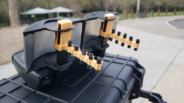 Figure 1. The 3D Printed 5.8 GHz "ParaYagi" Antennas on a DJI Spark Controller. |
||||||||||||||||||||||||||||||||||||||||||||||||||||||||||||||||||||||||||||||||||||||||||||||
|
|
|||||||||||||||||||||||||||||||||||||||||||||||||||||||||||||||||||||||||||||||||||||||||||||||
The Stock Dipole Antennas and their
4nec2 Models
|
|||||||||||||||||||||||||||||||||||||||||||||||||||||||||||||||||||||||||||||||||||||||||||||||
 |
 |
|---|---|
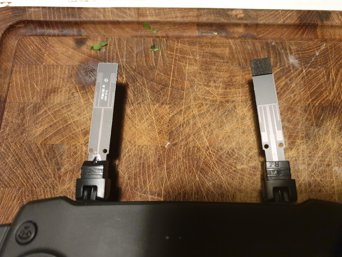
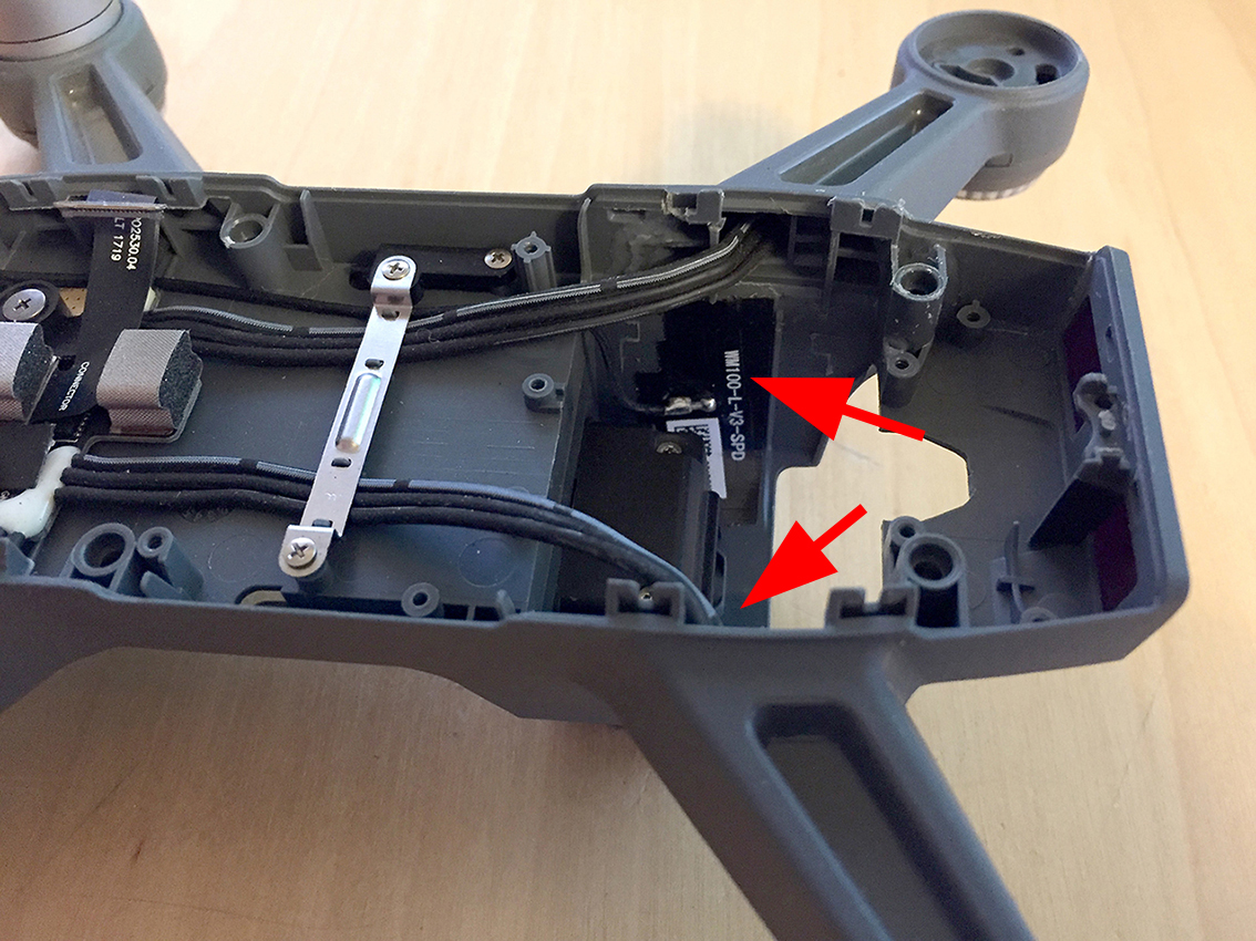
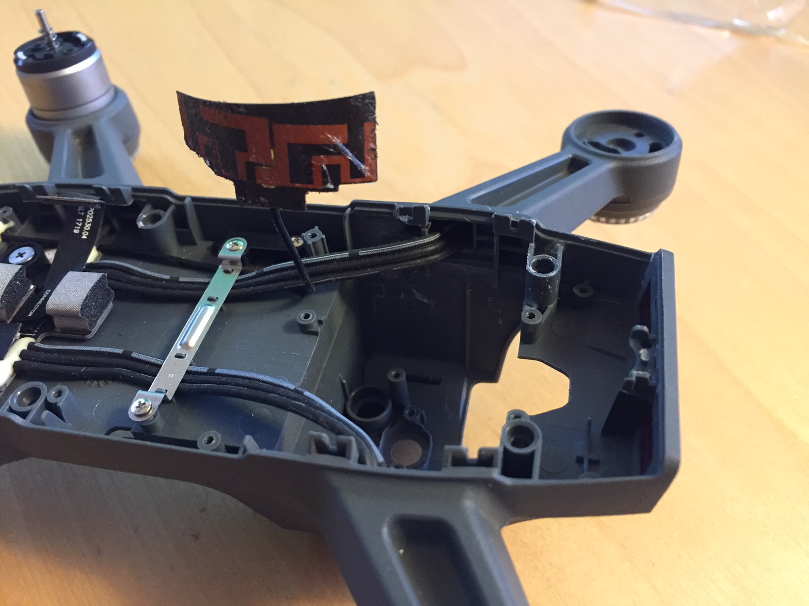
| Figure 2. The vertical whips of the DJI Mavic Mini controller.6 | Figures 3 & 4. The printed circuit 2.4/5.8 GHz vertical fan dipoles in the DJI Spark quadcopter.7 |
The dimensions are assigned to defined variables to
facilitate the future use of 4nec2's optimization
function on the models.
The dipole model lengths are selected to resonate
mid-band at 2.437 GHz and 5.785 GHz.
The dipoles are modeled with 3mm diameter to match the
Yagi elements. "Leg lengths" are one-half of the
full length of each element.
All element segmentation is selected to approximate the
4mm segment length of the "parabolic" reflector model.
|
|
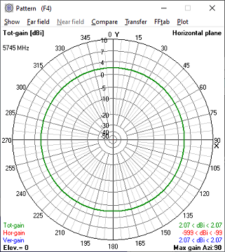
Figure 5. Dipole Horizontal Pattern
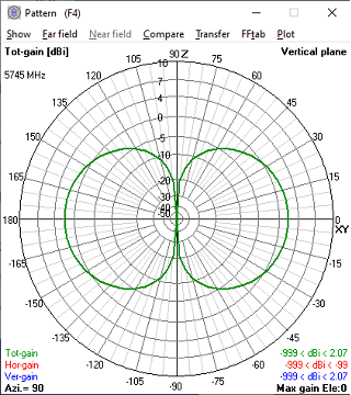
Figure 6. Dipole Vertical Radiation Pattern
The "Parabolic" Reflector Models
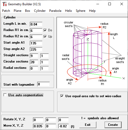
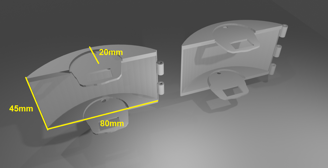
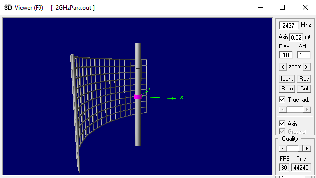
The 4nec2 Geometry Builder program is used to construct
the wire frame simulation model of the 90° reflector.
The reflector is truly cylindrical, not parabolic.
The reflector frame is 45mm high, but the height of the
metal reflector is 40mm with an 80mm aperture
width.
The center of the reflector is spaced 25mm behind the
dipole.
 |
 |
|---|---|
| Figure 7. The 3D "Parabolic" Reflector Model | Figure 8. The 4nec2 "Parabolic" Reflector Model |
In the 4nec2 model horizontal and vertical plane
radiation patterns and tables:
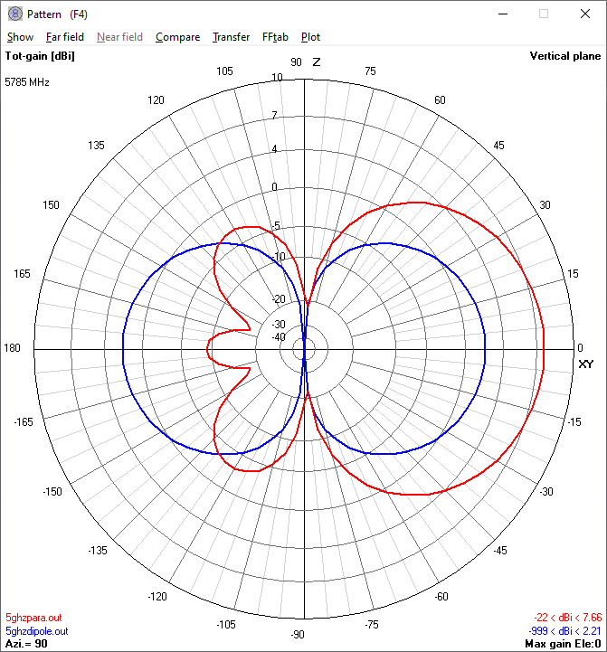
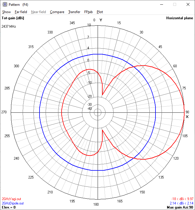
- The blue traces represent the stock antenna, and the red trace represent the comparison antenna.
- The effects of ground reflections are ignored.
- dBi is decibel gain over a theoretical isotropic
radiator.
- The desired heading is 90° in the horizontal plane and 0° in the vertical plane (to the right) in all cases.
- The 3 dB beamwidths are the angles from the maximum
at which gain is 3 dB down.
| "Parabolic"
Model Parameters |
2.4
GHz |
5.8
GHz |
|---|---|---|
| Maximum gain dBi |
5.04 |
7.66 |
| Maximum lobe direction |
270° (rear) |
90° |
| 3 dB Horizontal
Beamwidth |
±100° | ±20° |
| 3 dB Vertical
Beamwidth |
±33° | ±42° |
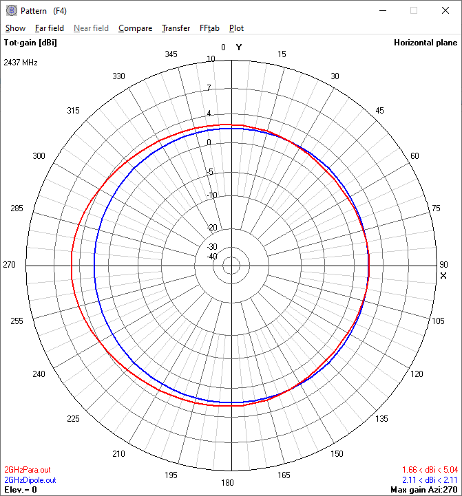
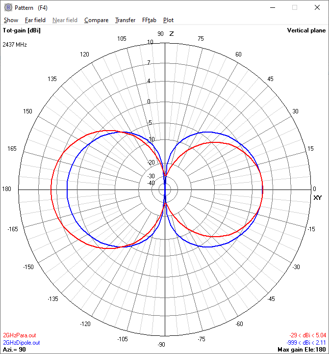
2.4 GHz "Parabolic" reflector horizontal and vertical radiation patterns compared to the stock dipole antenna.
At 2.4 GHz the "parabolic" reflector model shows equal
gain to the dipole in the forward 90° heading and 5.04
dBi gain towards the rear direction (270°).
This paradoxical behavior at 2.4 GHz would occur because
the reflector is vertically shorter than the half-wave
dipole. Likewise, this reflector's horizontal aperture
width is under one wavelength, too little for forward
gain.9
In agreement with this analysis, "DJI Alex" documented
no significant difference with the stock antennas or the
"parabolic" reflectors in his 2.4 GHz field test video
at https://youtu.be/3ALXqGrJxJ4?t=458.3
 |
 |
|---|---|
| Figure 10. The horizontal radiation pattern of the 2.4 GHz 'parabolic' reflector | Figure 11. The vertical radiation pattern of the 2.4 GHz 'parabolic' reflector |
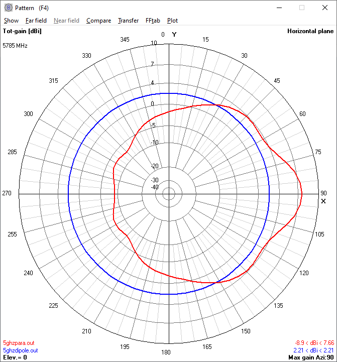
5.8 GHz "Parabolic" reflector horizontal and vertical radiation patterns compared to a dipole antenna.
At 5.8 GHz the 4nec2 model of the "parabolic"
reflector shows 5.4 dB gain over the dipole in the
desired direction.
The reflector's horizontal pattern displays most forward
gain is confined +/- 15° from the 90° desired
heading. Its vertical pattern shows significant
signal power is dispersed 30° above and below the
desired direction.
 |
 |
|---|---|
| Figure 12. The horizontal radiation pattern of the 5.8 GHz 'Parabolic' reflector | Figure 13. The vertical radiation pattern of the 5.8 GHz 'Parabolic' reflector |
The Yagi Antenna Models
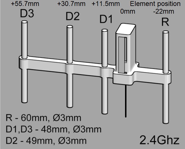
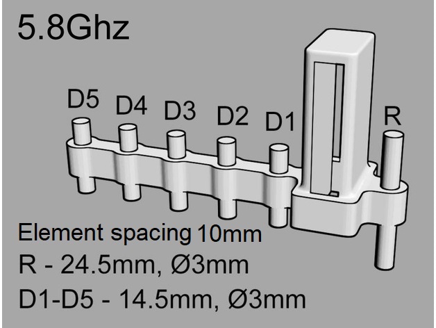
Here are the 3D model diagrams of the 2.4 GHz and 5.8
GHz Yagi antennas.
 |
 |
| Figure 14. 2.4 GHz Yagi 3D
Model |
Figure 15. 5.8 GHz Yagi 3D
Model |
|---|
| Variable
definitions |
Symbol | 2.4
GHz |
5.8
GHz |
|---|---|---|---|
| Dipole leg length
(m) Position (m) |
dr |
0.0277 0 |
0.01166 0 |
| Dipole and
reflector # of segments |
s | 13 |
7 |
| Directors # of segments |
s |
13 |
5 |
| Radius of elements
(m) |
rad |
0.0015 |
0.0015 |
| Reflector leg length (m) Position (m) |
r xr |
0.03 -0.022 |
0.01225 -0.01 |
| Director 1 leg length (m) Position (m) |
d1 xd1 |
0.024 +0.0115 |
0.00725 +0.01 |
| Director 2 leg length (m) Position (m) |
d2 xd2 |
0.0245 +0.0307 |
0.00725 +0.02 |
| Director 3 leg length (m) Position (m) |
d3 xd3 |
0.024 +0.0557 |
0.00725 +0.03 |
| Director 4 leg length (m) Position (m) |
d4 xd4 |
0.00725 +0.04 |
|
| Director 5 leg length (m) Position (m) |
d5 xd5 |
0.00725 +0.05 |
| Yagi
Antenna Model Characteristics |
2.4
GHz |
5.8
GHz |
|---|---|---|
| Maximum gain dBi |
9.97 |
10 |
| Maximum lobe direction |
90° |
90° |
| 3 dB Horizontal
Beamwidth |
±35° | ±34° |
| 3 dB Vertical
Beamwidth |
±27° | ±27° |
2.4 GHz Yagi horizontal and vertical radiation patterns compared to the stock dipole antenna.
The 2.4 GHz Yagi antenna exhibits 7.8 dB greater gain than the stock dipole antenna in the desired heading. The Yagi antenna offers approximately +/-30° focusing of the beam in both the horizontal and vertical planes."DJI Alex" documented greater than 2260m range with the Yagi compared to 1600m range with the stock dipole antenna in his field test video at https://youtu.be/3ALXqGrJxJ4?t=560.3
 |
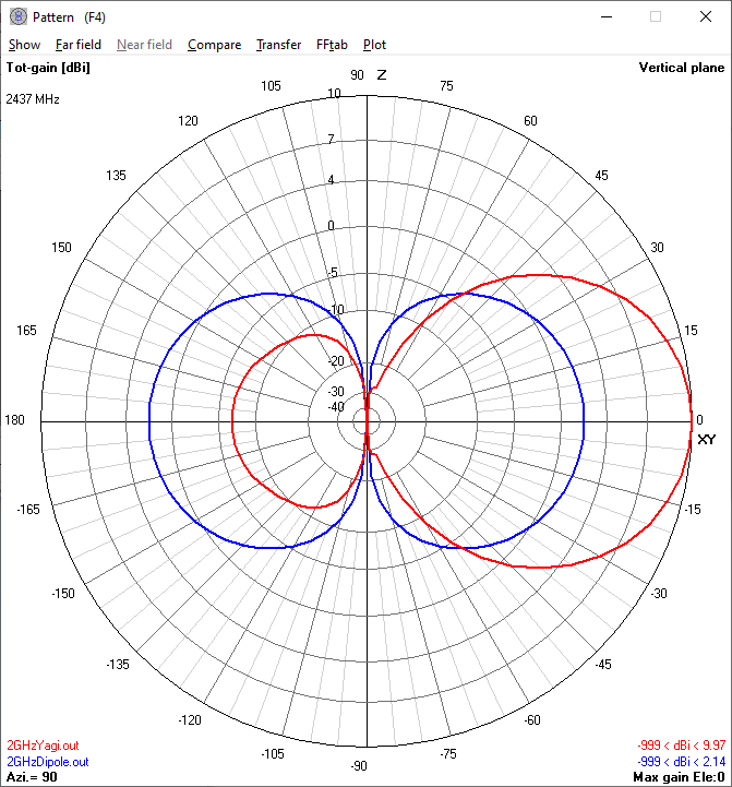 |
| Figure 15. The horizontal
radiation pattern of the 2.4 GHz Yagi antenna |
Figure 16. The vertical
radiation pattern of the 2.4 GHz Yagi antenna |
|---|
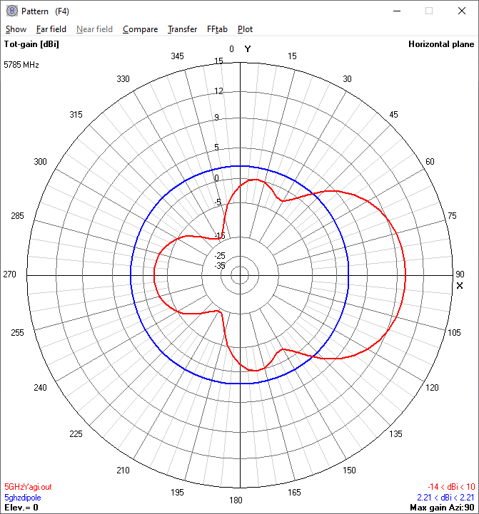
5.8 GHz Yagi horizontal and vertical radiation patterns compared to the stock dipole antenna.
At 5.8 GHz, the Yagi antenna exhibits 2.4 dB additional gain and better directivity compared to the "Parabolic" reflector. The Yagi antenna offers approximately +/-30° focusing of the beam in both the horizontal and vertical planes.Nick Daly demonstrated similar results in his 5.8 GHz comparison of the Yagi and parabolic reflector in his YouTube video https://www.youtube.com/watch?v=3JlziZsGBdM4
 |
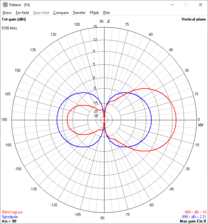 |
| Figure 17. The horizontal radiation pattern of the 5.8 GHz Yagi antenna | Figure 18. The horizontal radiation pattern of the 5.8 GHz Yagi antenna |
|---|
The "ParaYagi" Antenna Models
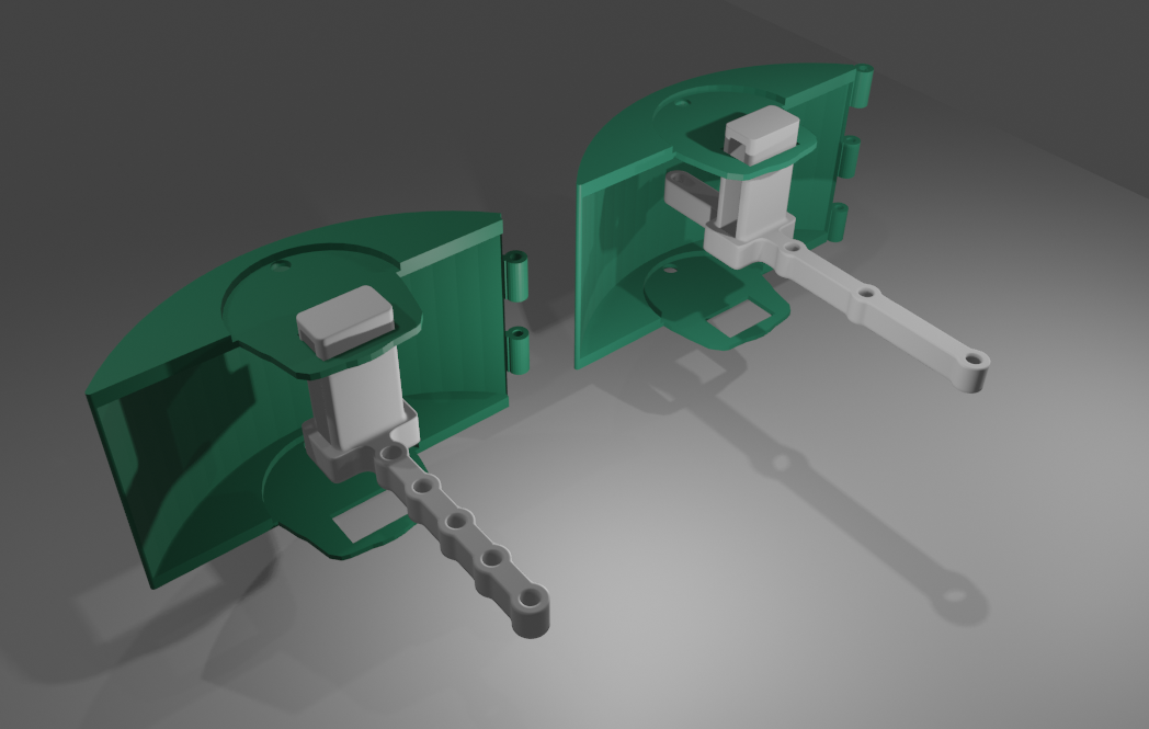
The "ParaYagi" models combine all the elements and
dimensions of the respective "parabolic" reflector and
the Yagi antenna models.
 |
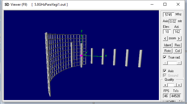 |
| Figure 19. 2.4 GHz and 5.8 GHz "ParaYagi" 3D Models | Figure 20. 5.8 GHz "ParaYagi" 4nec2 Model |
|---|
| "ParaYagi"
Model Characteristics |
2.4
GHz |
5.8
GHz |
|---|---|---|
| Maximum gain dBi |
9.79 |
10.4 |
| Maximum lobe direction |
90° |
90° |
| 3 dB Horizontal
Beamwidth |
±37° | ±30° |
| 3 dB Vertical
Beamwidth |
±26° | ±30° |
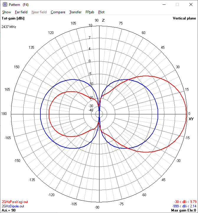
2.4 GHz "ParaYagi" Antenna horizontal and vertical radiation patterns compared to the stock dipole antenna.
At 2.4 GHz, adding the "parabolic" reflector slightly enlarges the rear lobe of the Yagi antenna pattern. The reflector adds no significant effect to 2.4 GHz Yagi antenna's forward gain and directivity.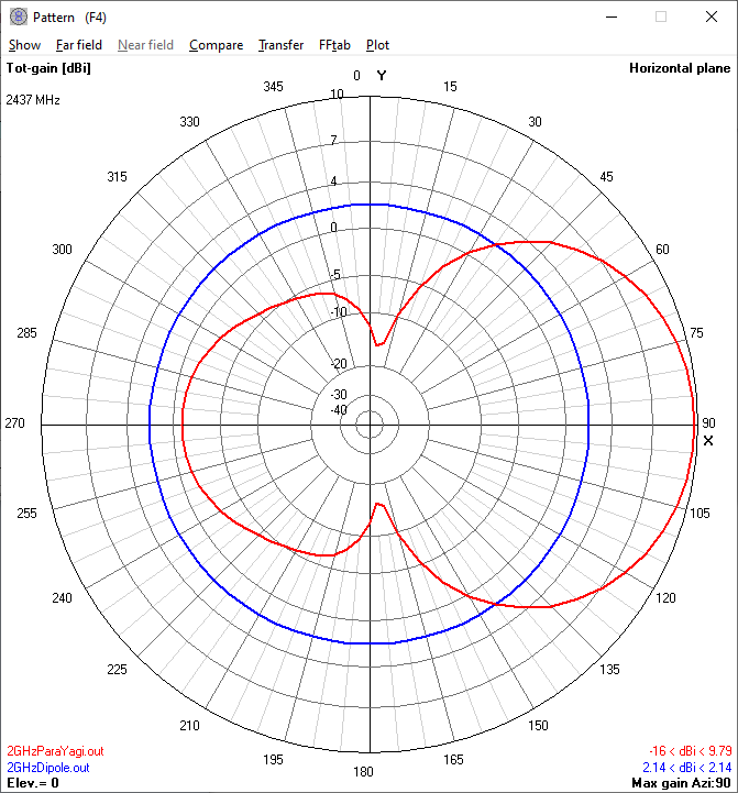 |
 |
| Figure 21. 2.4 GHz "ParaYagi"
Antenna horizontal radiation pattern |
Figurre 22. 2.4 GHz
"ParaYagi" Antenna vertical radiation pattern |
|---|
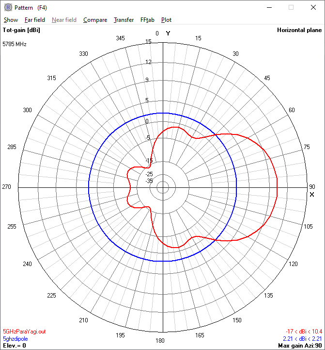
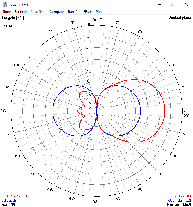
5.8 GHz "ParaYagi" Antenna horizontal and vertical radiation patterns compared to the stock dipole antenna.
At 5.8 GHz the "ParaYagi" combination antenna
suppresses the rear lobes of the Yagi antenna. The
addition of the reflector offers 0.4 dB increase in
forward gain over the Yagi antenna alone.
 |
 |
| Figure 23. 5.8 GHz "ParaYagi"
Antenna horizontal radiation pattern |
Figure 24. 5.8 GHz "ParaYagi" Antenna vertical radiation pattern |
|---|
Discussion
The observed field test signal strengths agree with the model prediction of greatest signal strength with the Yagi antennas and least signal strength with the stock dipole antennas.
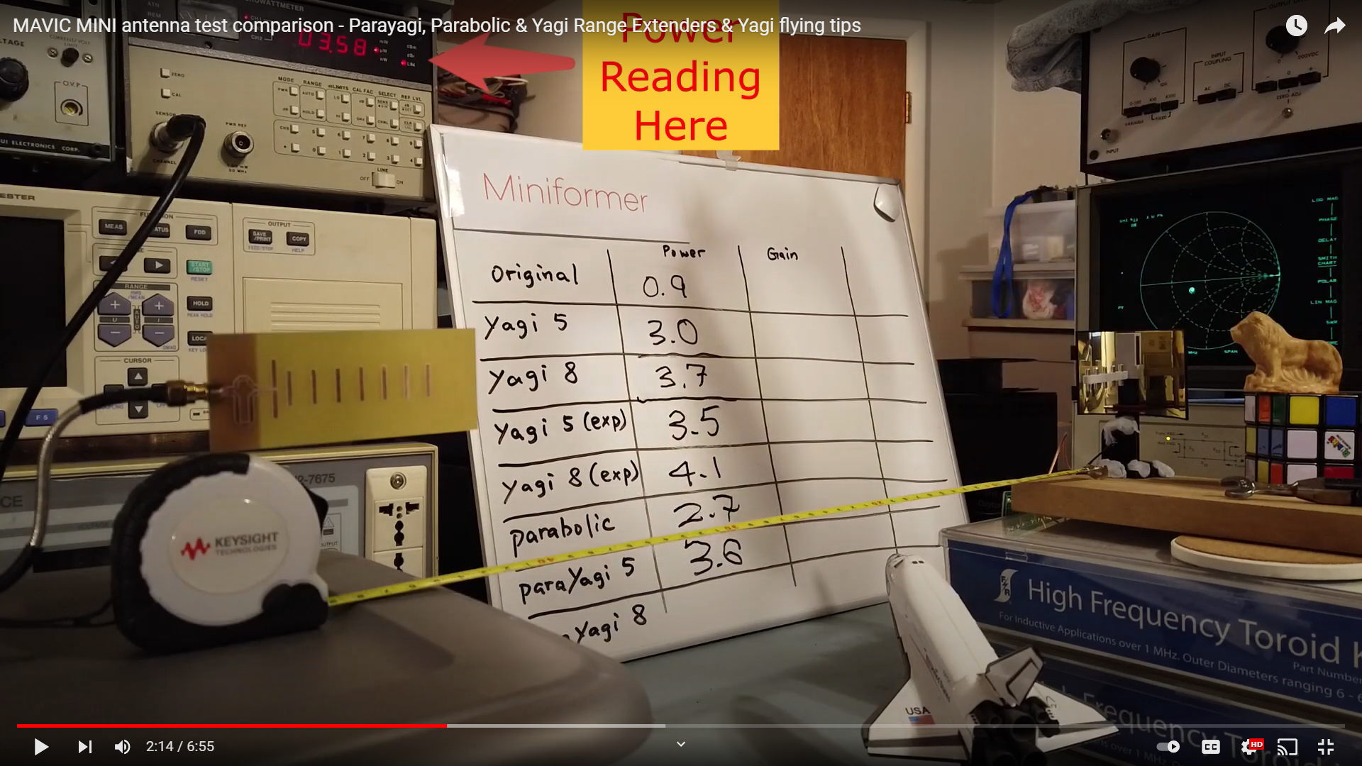
Miniformer published their laboratory gain measurements of various 5.8 GHz antenna extenders.10 Despite some errors introduced by their environmental variables, it is interesting to compare the Miniformer results against the 4nec2 model gain calculations for those antennas. Table 8 lists the Miniformer power measurements in microwatts, their dBu unit equivalents, and these values normalized to the 2.14 dB gain of the stock dipole antenna.
|
|
||||||||||||||||||||||||||||||||||||||||||||||||||||||||||||||||||||||||||||||||||||
|
|
 |
|---|---|
| MAVIC MINI antenna test comparison - Parayagi, Parabolic & Yagi Range Extenders | MAVIC MINI antenna test comparison - Parayagi, Parabolic & Yagi Range Extenders |
|
|
|
|---|---|
These data agree in that both the Yagi and ParaYagi antennas exhibit greater gain than the Parabolic antenna with no greater than 3.5 dB variance between expected and observed values.
Conclusions
- The "Parabolic" reflector offers a moderate
contribution to the forward gain and directivity of
the stock antenna at 5.8 GHz. The reflector
contributes no significant effect to the stock antenna
at 2.4 GHz.
- The Yagi antenna provides improved signal gain and directivity over a "Parabolic" reflector at both 2.4 GHz and 5.8 GHz.
- The "Parabolic" reflector exerts little additional effect when combined with the 2.4 GHz Yagi antenna. At 5.8 GHz, adding the "Parabolic" reflector suppresses the rear lobes of the Yagi antenna pattern.
I now rarely observe signal dropouts and video feed lag
in my field tests with the 5.8 GHz Yagi or ParaYagi
antennas. While flying at a distance, I have
observed loss of signal when I divert the antennas more
than 30° vertically or horizontally from the direction
of the quadcopter. The stable and correct aim of
these directional antennas is increasingly important for
flight control over greater distances.
References
- Radio Control, Wikipedia
- PARAYAGI P2
Extender, Ali Vekta, Thingiverse, 7 July 2021
DIY Range Extenders VS Parabolic - MAVIC MINI, DJI Alex, 15 May 2020 Parabolic Mirrors vs Yagi Antennas | Mavic Mini Video Comparison, Nick Daly, 21 June 2020 - 4nec2 antenna modeling software, Voors, A.
- DJI Mavic Mini Controller Antenna, DJI Mavic Mini Forum, 15 May 2020
- DJI Spark Internal Antenna, DJI Spark Forum, 29 Jan 2018
- DJI FCC Specifications and
Compliance Reports, https://www.fccid.io/SS3
- Antenna Aperture, Wikipedia
- Mavic Mini
Antenna Test Comparison - Parayagi, Parabolic &
Yagi Range Extenders, Miniformer, 2 July 2020
Appendix
| 4nec2 Models | 2.4 GHz | 5.8 GHz |
|---|---|---|
| Dipole |
2GHzDipole.nec |
5GHzDipole.nec |
| Parabolic |
2GHzPara.nec |
5GHzPara.nec |
| Yagi |
2GHzYagi.nec | 5GHzYagi.nec |
| ParaYagi |
2GHzParaYagi.nec | 5GHzParaYagi.nec |
