Signal Level Measurement with PowerSDR and External
Transverters
|
||||||||||||||||||||||||||||||||||||||||||||||||||||||||||||||||||
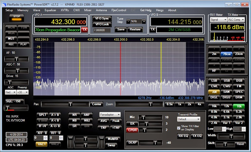
INTRODUCTIONThis object of this study was to obtain accurate signal and noise floor measurement using a FlexRadio 1500 transceiver1 with external transverters. The transverters were an Elecraft XV1442 for 144 MHz and a Down East Microwave L432-28HP3 for 432 MHz with an intermediate frequency output of 28 MHz. The manufacturers specify the Elecraft XV144 nominal conversion gain as 25 dB and noise figure as 0.8 dB, while the Downeast Microwave L432-28HP's nominal gain is 17 dB and noise figure is <1 dB. In the PowerSDR software that is used with the FlexRadio 1500, the external transverter parameters are specified through the setup form that is accessed with the Alt-X key combination. The accuracy of the PowerSDR RX1 receive signal meter depends on entering the correct value of "RX Gain (dB)" that represents the transverter conversion gain. With a single frequency source of known amplitude applied to the receiver, one may determine the correct value for RX Gain (dB) by adjusting it until the receive signal meter indicates the known power level. This study used an alternate method, a wideband RF noise source, to accurately characterize these transverter parameters. CALIBRATING THE TRANSVERTERSAt room temperature, a 50 ohm resistor produces -174 dBm/Hz of noise. The noise power in a given bandwidth is proportional to the bandwidth. This yields a noise power of -154 dBm in 100 Hz, -144 dBm in 1 kHz and -134 dBm in 10 kHz, etc. The RF Gadgets XDM-1600 noise source4 was determined (with a miniVNA Pro vector network analyzer) to have an output impedance of 50 ohms and its noise output level had been calibrated by the manufacturer against an HP 8970B noise figure meter as 15.2 dB ENR (excess noise ratio) at 150 MHz and 15.3 dB ENR at 450 MHz. When this noise source is attached to the transverter antenna connector, the receiver should indicate a noise power equal to this ENR added to -174 dBm/Hz. For example, with the PowerSDR set to a bandwidth of 10 kHz, the receiver should indicate -118.8 dBm (-134 dBm + 15.2 dB ENR) noise power on 144 MHz and -118.7 dBm (-134 dBm + 15.3 dB ENR) noise power on 432 MHz. For these measurements the noise source was powered with three 9 volt carbon zinc batteries connected in series to provide 27 volts and its output was attached directly to the antenna input connector of each transverter. PowerSDR was set to a bandwidth of 10 kHz, the RX1 Meter set to "Signal" and the Preamp set to +30. With the noise source turned on, it was found that on 144 MHz an "RX Gain dB" of 26.5 dB yielded the expected noise power reading of -118.8 dBm, and on 432 MHz an "RX Gain dB" of 24.1 dB yielded a noise power reading of -118.7 dBm. The noise power measurements with the attached noise source turned off were -132.1 dBm on 144 MHz and -131.7 dBm on 432 MHz. When these measurements were repeated within bandwidths of 1 kHz and 100 Hz, they yielded the corresponding 10 dB and 20 dB decreases in noise power as expected. The difference between the noise power with the noise source turned on and off is called the "Y factor", a quantity used to calculate the noise figure. The Y factor was 13.3 on 144 MHz and 13 dB on 432 MHz. The formula to calculate noise figure (dB) using the Y factor5 is: Noise Figure (NF) = 10�log((Y/10)/(ENR/10-1)) yielding the noise figure values shown in Table 1 below.
With this calibration, PowerSDR will indicate accurate received signal levels in dBm. However, the S-meter will continue to indicate S9 for -73 dBm instead of the alternate -93 dBm standard for VHF and UHF. Therefore, one must add 3.3 S Units to render accurate S meter readings on VHF and higher frequencies.6 NOISE FLOOR MEASUREMENTSOnce the transverters have been calibrated for conversion gain, it is possible to accurately measure the environmental RF noise level. Table 2 shows the noise power within a 10 kHz bandwidth first measured with a 50 ohm resistor attached to the transverter antenna connector, then with an external antenna connected. These values are also adjusted to the standard 1 Hz bandwidth.
|
||||||||||||||||||||||||||||||||||||||||||||||||||||||||||||||||||
REFERENCES |
||||||||||||||||||||||||||||||||||||||||||||||||||||||||||||||||||

