An Elliptical Medium Wave Bandstop Filter in an Altoids BoxDesign and Construction of an Elliptical Medium Wave Band Stop Filterby Dr. Carol F. Milazzo, KP4MD (posted 24 May 2014, last updated 27 October 2024) INTRODUCTIONMonitoring non-directional beacons (NDBs) and other transmissions on frequencies below 530 kHz and above 1700 kHz and reception on direct conversion receivers may be difficult in urban locations due to the overloading of the receiver front end by nearby powerful AM broadcast transmitters in the 530-1700 kHz medium frequency band. I reside in the Sacramento, California area, within 15 miles of several medium wave broadcast stations with high local field strengths due to their transmitter power and proximity1 (see Table 1). These all produce strong images and intermodulation products that have interfered with the reception of signals below 540 kHz and front-end overload on reception above 1700 kHz. |
|
|
|---|---|---|
|
A 5-pole Chebyshev low pass
filter2 that I had previously designed
did not provide sufficient attenuation of strong medium
wave broadcast signals below 1 MHz. Elliptical
bandstop filters demonstrate frequency response with
sharp maxima of attenuation at the specific frequencies
of their resonant LC circuits. This design
appeared to offer a feasible solution to achieve the
required attenuation to suppress receiver overload and
interfering intermodulation products. This article describes the construction of a low cost
elliptical bandstop filter that was designed to reduce
interference from medium wave AM broadcast
stations. It is suitable for use with
communications receivers and some low power
transmitters. This construction technique may be
adapted for filters on other frequency ranges. |
|
|
DESIGNING THE FILTERSIn 1984 I had written, published and explained two
BASIC language computer programs3,4 for the
design of Butterworth and Chebyshev filters. Since
then numerous filter design programs and calculators
have become available on the internet. From these,
I selected the AADE
Filter Design and Analysis software by Almost All
Digital Electronics.5 I started with an
elliptical bandstop filter design by Kratoska6
and varied the inductor values to provide resonances and
peak attenuation on 650, 1320 and 1530 kHz. I
designed a 3-pole and a 5-pole version of the elliptic
filter for comparison purposes. The software yielded the component values and response
curves in Figures 4 and 6. The circuits required
1200 pF and 2200 pF 50 volt ceramic disc capacitors, and
3.3, 4.9 and 50 μH inductors. Two of the 2200 pF
capacitors are connected in parallel to make the 4400 pF
capacitor. Download
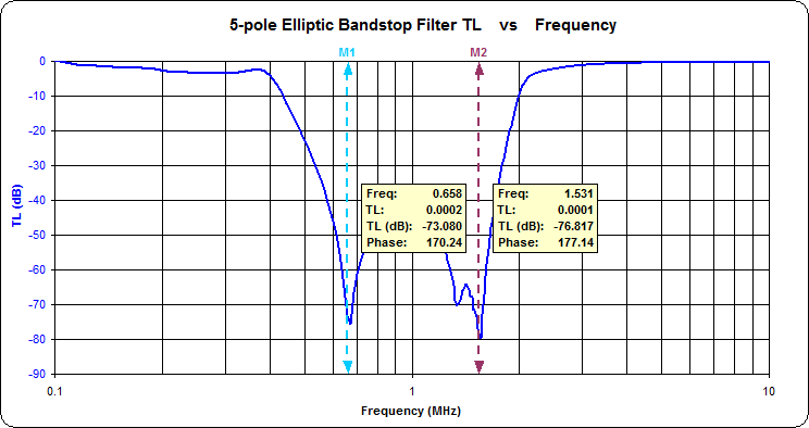
the 5-pole filter design file. BUILDING THE FILTERSThe filters were built inside a 20 mm x 58 mm x 93 mm recyclable steel Altoids mints box (Figure 3). This box had appropriate dimensions, was easily machined and had easily soldered surfaces. Northrup has also constructed various projects with these boxes.7 The online calculator at http://toroids.info/8 was used to determine the number of windings that were required for the inductors. Using 24 AWG enameled wire, the 50 μH coils required 12 turns of wire on FT37-43 cores, the 4.9 μH coils required 20 turns on T37-3 cores and 3.3 μH coil required 17 turns on a T37-3 toroid core. First, each individual LC resonant circuit was assembled and its coil spacing adjusted to obtain the corresponding resonant frequencies of 650, 1320 and 1530 kHz. This was required due to the tolerance variation of the capacitors. Then, each filter circuit was then assembled and tested with a miniVNA Pro vector network analyzer and signal strengths measured with a Flex-3000 receiver tuned to the frequencies under study. Figures 1 and 2 show the ugly construction and finished assembly of the 5-pole filter. After initial testing, I designed a custom printed circuit board to fit the "ugly construction" 5-pole filter into the Altoids box. I used an Exacto knife to cut pads in a 72mm x 54mm copper clad board, trimmed the component leads and soldered all parts on the board. See Medium Wave Bandstop Filter photo album for details. FILTER OPERATIONFigures 5 and 7 shows the measured attenuation in
decibels for each filter over the frequency range from
100 kHz to 10 MHz. The 3-pole filter yielded -30
dB attenuation at 650 kHz, -29 dB at 1320 kHz and -52 dB
at 1530 kHz with a minimum of -18 dB at 960 kHz.
The 5-pole filter yielded -73 dB attenuation at 650 kHz,
-69 dB at 1320 kHz and -77 dB at 1530 kHz with a minimum
of -42 dB at 940 kHz. Table 1 lists and charts the comparative signal strengths of the received signals measured with a FlexRadio FLEX-3000 receiver with and without this 5-pole Elliptical bandstop filter and a 5-pole Chebyshev low pass filter. The filter attenuations listed for each frequency were calculated as the difference in received signal strengths with and without each filter. Receiver panadapter displays that demonstrate the reduction of intermodulation product interference may be seen in the photo album. CONCLUSION: This 5-pole elliptical
bandstop filter designed for maximum attenuation of
strong medium wave signal frequencies was superior to
the 5-pole Chebyshev low pass filter in suppression of
interference from intermodulation products and receiver
overload from medium wave broadcasts. Medium wave bandstop filters are also commercially available9. |
Figure 1. 5-pole Elliptical Bandstop Filter Ugly Construction |
|
| Figure 2. 5-pole Bandstop Filter Finished Construction |
||
| |
Table 1. Received Signal Strengths and Filter Attenuation vs. Frequency |
Figure 3. Schematic Diagram and Component Values |

Figure 4. 3-pole Elliptical Bandstop Filter Model and Calculated Frequency Response Curve |
 Figure 5. VNA measured filter response curve of the 3-pole Elliptical Bandstop filter. |
|---|---|
 Figure 6. 5-pole Elliptical Bandstop Filter Model and Calculated Frequency Response Curve |
 Figure 7. VNA measured filter response curve of the 5-pole Elliptical Bandstop filter. |
REFERENCES
|
|