Magnetic Loop Antenna Parameters: 7-30 MHz
|
|||||||||||||||||||||||||||||||||||||||||||||||||||||||||||||||||||||||||||||
|
1. This curve of the measured SWR demonstrates the 23 kHz 2:1 VSWR bandwidth of the Magnetic Loop antenna when the capacitor is adjusted to resonance near 7.103 MHz. The antenna should function satisfactorily within 12 kHz of this resonant frequency and significantly decrease noise and interference from undesired signals outside of this frequency range. The capacitor requires adjustment for operation on frequencies outside of this range. |
|||||||||||||||||||||||||||||||||||||||||||||||||||||||||||||||||||||||||||||
|---|---|---|---|---|---|---|---|---|---|---|---|---|---|---|---|---|---|---|---|---|---|---|---|---|---|---|---|---|---|---|---|---|---|---|---|---|---|---|---|---|---|---|---|---|---|---|---|---|---|---|---|---|---|---|---|---|---|---|---|---|---|---|---|---|---|---|---|---|---|---|---|---|---|---|---|---|---|
|
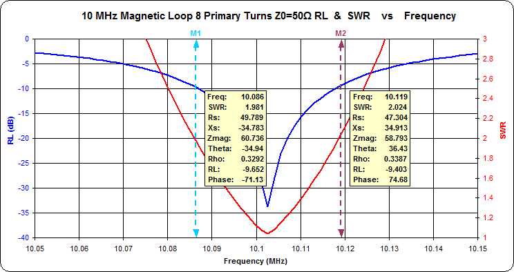
2. This curve of the measured SWR demonstrates the 33 kHz 2:1 VSWR bandwidth of the Magnetic Loop antenna when the capacitor is adjusted to resonance near 10.102 MHz. The antenna should function satisfactorily within 16 kHz of this resonant frequency and significantly decrease noise and interference from undesired signals outside of this frequency range. The capacitor requires adjustment for operation on frequencies outside of this range. |
|||||||||||||||||||||||||||||||||||||||||||||||||||||||||||||||||||||||||||||
|
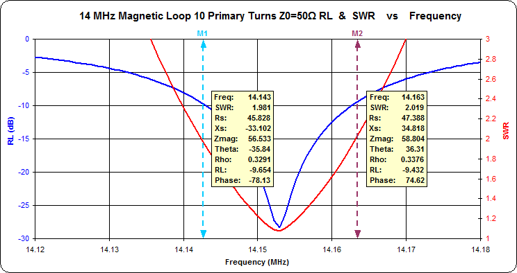
3. This curve of the measured SWR demonstrates the 20 kHz 2:1 VSWR bandwidth of the Magnetic Loop antenna when the capacitor is adjusted to resonance near 14.153 MHz. The antenna should function satisfactorily within 10 kHz of this resonant frequency and significantly decrease noise and interference from undesired signals outside of this frequency range. The capacitor requires adjustment for operation on frequencies outside of this range. |
|||||||||||||||||||||||||||||||||||||||||||||||||||||||||||||||||||||||||||||
|
4. This curve of the measured SWR demonstrates the 33 kHz 2:1 VSWR bandwidth of the Magnetic Loop antenna when the capacitor is adjusted to resonance near 18.1 MHz. The antenna should function satisfactorily within 16 kHz of this resonant frequency and significantly decrease noise and interference from undesired signals outside of this frequency range. The capacitor requires adjustment for operation on frequencies outside of this range. |
|||||||||||||||||||||||||||||||||||||||||||||||||||||||||||||||||||||||||||||
|
5. This curve of the measured SWR demonstrates the 39 kHz 2:1 VSWR bandwidth of the Magnetic Loop antenna when the capacitor is adjusted to resonance near 21.201 MHz. The antenna should function satisfactorily within 20 kHz of this resonant frequency and significantly decrease noise and interference from undesired signals outside of this frequency range. The capacitor requires adjustment for operation on frequencies outside of this range. |
|||||||||||||||||||||||||||||||||||||||||||||||||||||||||||||||||||||||||||||
|
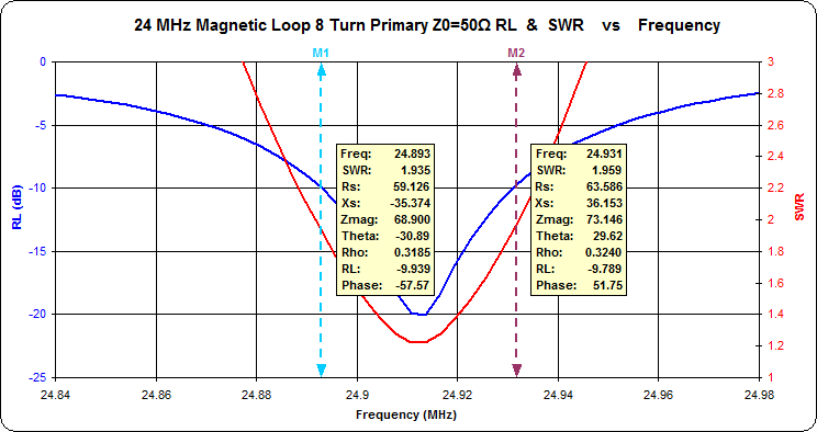
6. This curve of the measured SWR demonstrates the 38 kHz 2:1 VSWR bandwidth of the Magnetic Loop antenna when the capacitor is adjusted to resonance near 24.913 MHz. The antenna should function satisfactorily within 19 kHz of this resonant frequency and significantly decrease noise and interference from undesired signals outside of this frequency range. The capacitor requires adjustment for operation on frequencies outside of this range. |
|||||||||||||||||||||||||||||||||||||||||||||||||||||||||||||||||||||||||||||
|
7. This curve of the measured SWR demonstrates the 76 kHz 2:1 VSWR bandwidth of the Magnetic Loop antenna when the capacitor is adjusted to resonance near 28.405 MHz. The antenna should function satisfactorily within 38 kHz of this resonant frequency and significantly decrease noise and interference from undesired signals outside of this frequency range. The capacitor requires adjustment for operation on frequencies outside of this range. |
|||||||||||||||||||||||||||||||||||||||||||||||||||||||||||||||||||||||||||||
|
8. Plot of measured Magnetic Loop Antenna Feed Point
Impedance vs. Frequency. Comparison of feed point
impedances at 5 through 11 primary turns on the FT114-43
ferrite core. VSWR < 1.2:1 from 42 to 60 ohms
impedance. The measurements on 14-28 MHz were taken
with only the air variable tuning capacitor on the loop
antenna. The curves are skewed on 7 and 10 MHz due
to the attachment of the lossy 150 pF or 60 pF shunt
coaxial capacitors respectively on those frequencies.
|
|||||||||||||||||||||||||||||||||||||||||||||||||||||||||||||||||||||||||||||
|
9. Plot of measured 2:1 VSWR bandwidth vs.
frequency. The bandwidth values for 7 MHz and 10 MHz
are higher than at other frequencies due to the lossiness
of the shunt coaxial capacitors.
|
|||||||||||||||||||||||||||||||||||||||||||||||||||||||||||||||||||||||||||||
|
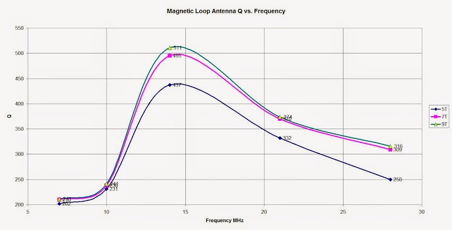
10. Plot of calculated Magnetic Loop Antenna Q vs. Frequency. The Q values for 7 MHz and 10 MHz are lower than at other frequencies due to the lossiness of the shunt coaxial capacitors used on those frequencies. (Calculator on http://owenduffy.net/calc/VswrBw2AntQ.htm) |
|||||||||||||||||||||||||||||||||||||||||||||||||||||||||||||||||||||||||||||
|
11. Plot of calculated Magnetic Loop Antenna Free Space Efficiency vs. Frequency. (Calculator at http://owenduffy.net/calc/SmallTransmittingLoopBw2Gain.htm)
|
|||||||||||||||||||||||||||||||||||||||||||||||||||||||||||||||||||||||||||||
|
12. Plot of calculatated Magnetic Loop Antenna Free Space Gain vs. Frequency. (Calculator at http://owenduffy.net/calc/SmallTransmittingLoopBw2Gain.htm) |
|||||||||||||||||||||||||||||||||||||||||||||||||||||||||||||||||||||||||||||
|
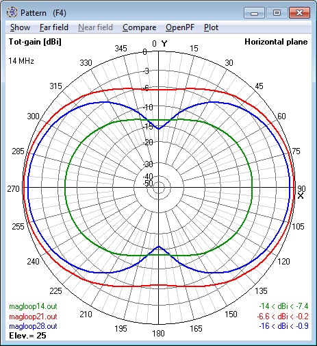
13. Azimuth Radiation
Patterns for Magnetic Loop Antenna modeled for 14, 21
and 28 MHz at 5 feet above Average Ground (4nec2 model). |
14. Elevation Radiation Patterns for Magnetic Loop Antenna modeled for 14, 21 and 28 MHz at 5 feet above Average Ground (4nec2 model). |
||||||||||||||||||||||||||||||||||||||||||||||||||||||||||||||||||||||||||||
|
|
|||||||||||||||||||||||||||||||||||||||||||||||||||||||||||||||||||||||||||||
SPECIFICATIONS AT RESONANCEImpedance: 50 ohms non-reactive nominal
*A fixed capacitor connected in parallel across the butterfly capacitor allowed operation over either the 7 MHz or 10.1 MHz bands. These capacitors should be rated at 5 kV or better for 30 watt transmissions. |
ANTENNA PARAMETERS: Measured vs. NEC Model
|
||||||||||||||||||||||||||||||||||||||||||||||||||||||||||||||||||||||||||||
| Frequency. MHz |
2:1 SWR BW kHz |
Q | Eff. %* | Eff. %** per Model |
Free Space* Gain dBi |
Gain dBi** per Model |
|---|---|---|---|---|---|---|
| 28.4 | 76 | 271 | 56.7 | 66.1 | -0.7 | -0.2 |
| 24.9 | 50 | 374 | 52.7 | 54.5 | -1.0 | -1.1 |
| 21.2 | 39 | 398 | 33.4 | 37.1 | -3.0 | -2.7 |
| 18.1 | 32 | 399 | 21.7 | 24.4 | -4.9 | -4.5 |
| 14.15 | 20 | 498 | 12.9 | 11.3 | -7.1 | -7.8 |
| 10.1*** | 33 | 221 | 2.1 | 3.7 | -15.1 | -13 |
| 7.1*** | 23 | 198 | 0.6 | 1.1 | -20.1 | -18 |
* Antenna
Q, Efficiency
and Free Space Gain dBi derived from measured data
with calculators by Owen Duffy.
** Efficiency and Free Space Gain dBi per Model
calculated with the specified parameters for the NEC
model.
*** The lossy coaxial shunt capacitors used on 7 and 10
MHz would account for the lower measured Q, efficiency
and gain than the NEC model predictions for those
frequencies.
CONCLUSION
The correlation of the measured parameters with those predicted by the 4nec2 Method of Moments calculations validate the magnetic loop antenna models.
REFERENCES
- Magnetic Loop Antenna for 80-20 Meters, Doerenberg, F, N4SPP
- Calculate Antenna Q from VSWR bandwidth measurement, Duffy, O, VK2OMD
- Calculate small transmitting loop gain from bandwidth measurement, Duffy, O, VK2OMD
- Ground effects on KP4MD�s 0.9m loop on 28MHz, Duffy, O, VK2OMD
- Portable Magnetic Loop Antenna Version Two, Goff, R, G4FON
- Small High Efficiency Loop Antennas, Hart, T, W5QJR
- ZPLOTS Impedance Plots Using Excel Charts, Maguire D, AC6LA
- A Universal HF Magnetic Loop NEC Model, Milazzo, C, KP4MD
- Small Transmitting Loop Antennas, Yates, S, AA5TB
- Magnetic Loop Antenna Project, River City Amateur Radio Communications Society
LINKS |
ZPLOTS
DATA FILES
|


