Aligning the Henry Radio 30A02 RF Amplifier

VHF Band Class C RF Power Amplifier

by Dr. Carol F. Milazzo, KP4MD (posted 04 September 2011)
E-mail: [email protected]

The Henry Radio 30A02 (aka Tempo S-30) is a Class C RF amplifier with the following manufacturer's specifications:

Table 1.  Henry Radio 30A02
RF Amplifier Specifications
Model
30A02
Watts In/Out 5-30 Mobile
Frequency range
136-174 MHz
Bandwidth
5 MHz approx.
Mode
FM only (Class C)
Volts/amps
+13.8 vdc - 7 amps
Dimensions
4"W x 4"H x 5.5"D
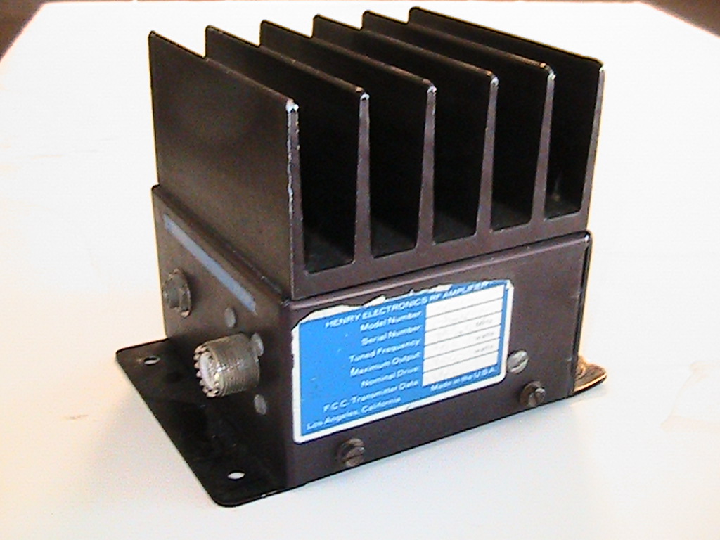
Henry Radio 30A02 RF Amplifier
Figure 1. Henry Radio 30A02 RF Amplifier

CONTENTS
Henry Radio 30A02
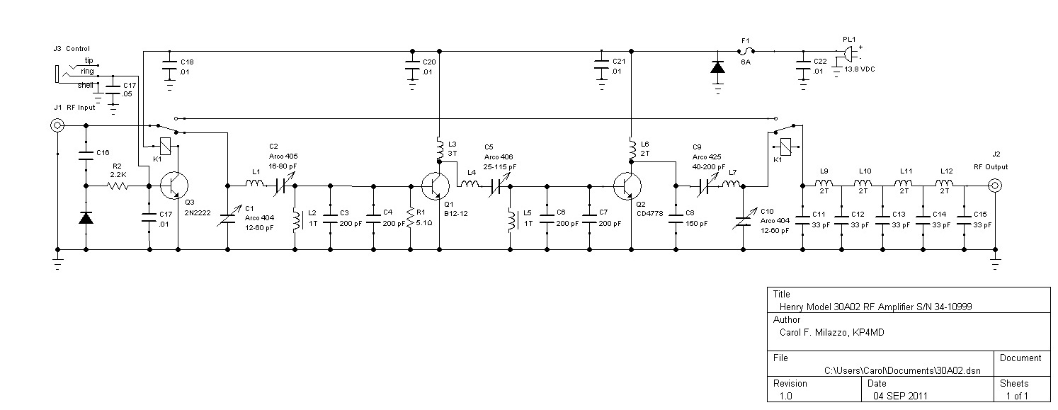
                    RF Amplifier Schematic Diagram
Figure 2. Henry Radio 30A02 RF Amplifier Schematic Diagram

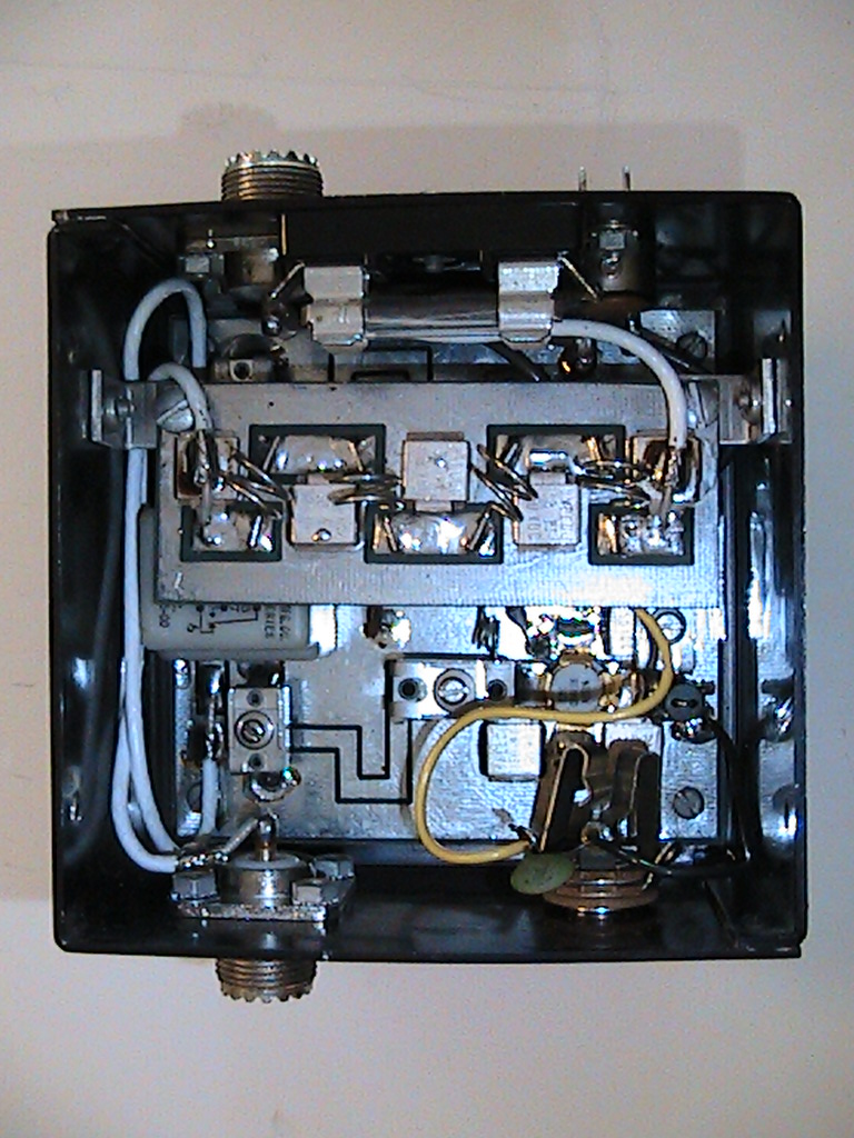
Figure 3. Henry Radio
                30A02 bottom cover removed
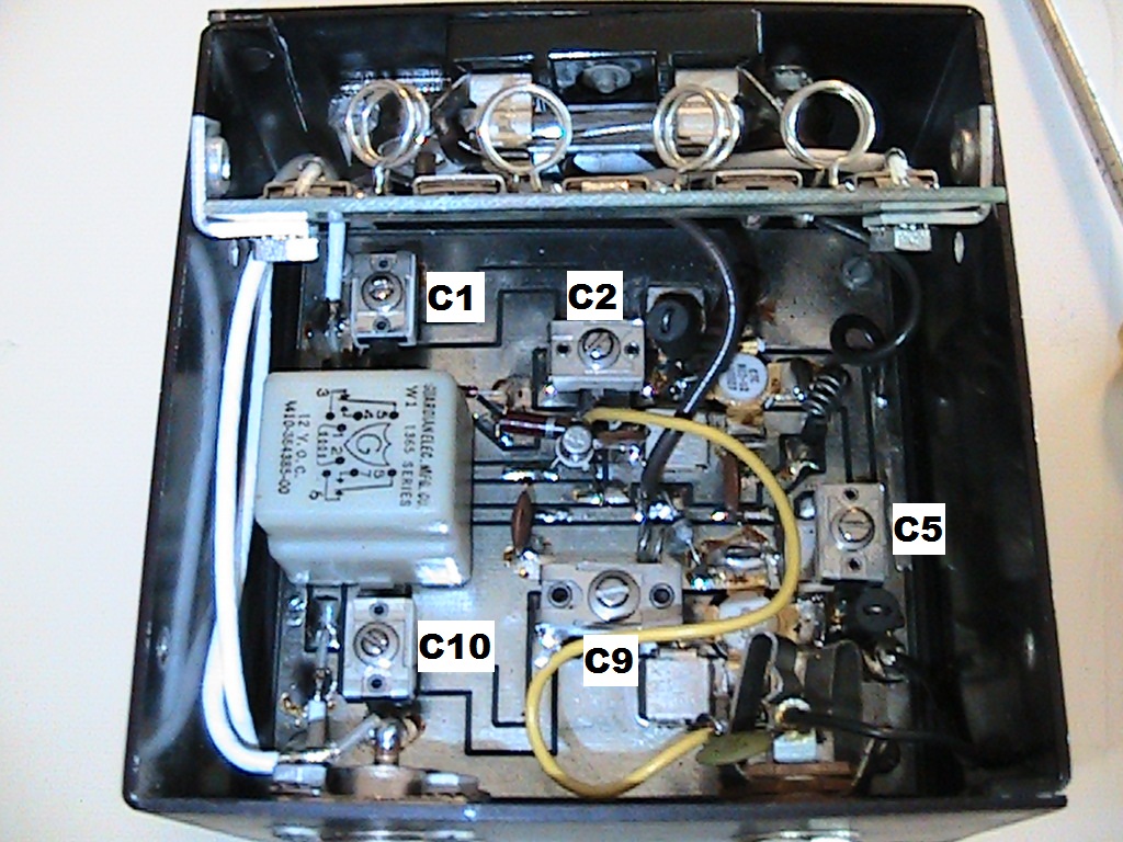
Figure 4. Henry Radio
                30A02 Alignment Controls - low pass assembly flipped up
Figure 3. Henry Radio 30A02 bottom cover removed
Figure 4. Henry Radio 30A02 Alignment Controls - the low pass filter assembly has been flipped up

Alignment Procedure

  1. Use a non-metallic alignment tool.
  2. Connect the exciter through an SWR bridge to the amplifier RF input.
  3. Connect the amplifier RF output through a relative power meter to a 50 ohm load.
  4. Remove the bottom cover of the amplifier with its four hex head screws.
  5. Loosen the two screws that hold the low pass filter assembly and flip it up to access C1 and C2 (see Figure 4).
  6. Apply power and while transmitting adjust C1 and C2 for the minimum reflected power on the RF input.
  7. Adjust C5 for maximum RF output from the amplifier.
  8. Adjust C9 and C10 for the minimum DC current and maximum output power from the amplifier.
  9. Stop transmitting and reduce C5 to enough to eliminate any oscillation that occurs in the receive mode (see Note 1).
  10. Repeat the steps 6 through 9 as these adjustments show some interaction.

Notes

  1. I have seen the amplifier go into oscillation with the incorrect adjustment of C5.  When this occurs after switching from transmit to receive, the amplifier will continue to draw high currrent and generate a strong radio frequency noise that desenses the receiver.  This oscillation will stop each time the power source is disconnected.
  2. The low-pass filter section is always in the circuit and will attenuate signals above 174 MHz during both transmission and reception.


REFERENCES

  1. Henry Radio Amplifiers
  2. Henry Radio C30A Amplifier Manual
  3. TPL VHF (Hi-Band) Power Amplifier 136-175 MHz Owners Manual
Return to KP4MD Home Page
Top