The Balcony Mounted Magnetic Loop Antenna
A NEC Model Comparative Analysis of Physical Orientation
and Performance
by Dr. Carol F. Milazzo, KP4MD (posted 12 June 2015)
E-mail: [email protected]
INTRODUCTION
The small magnetic loop is a useful compromise antenna for
limited space and portability. For this reason, the
magnetic loop antenna is a practical high frequency antenna
solution for the restricted space of apartment dwellers.
Little has been written on the effect of antenna orientation on
performance in this scenario. This study presents a
comparative 4nec21 model analysis on the effect of
orientation of magnetic loop antennas mounted on an apartment
building window or balcony with regard to antenna radiation
pattern and efficiency.
1. High rise apartment building
|
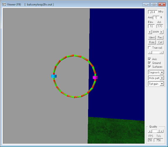
2. 4nec2 model geometry
|
3. Horizontal orientation
|
4. Vertical orientation
|
5. The magnetic loop antenna in the red circle,
showing its low profile. |
6. Magnetic loop antenna. Vertical orientation.
Northwest view towards North America. |
MODEL DESIGN
The problem was to compare the performance of a Chameleon CHA
F-Loop Antenna, a 0.74 m (2.44 feet) diameter radiator
loop of DX Engineering DXE-400 MAX brand of LMR-400 coaxial
cable, mounted either horizontally or vertically on a balcony
railing near the center of the high rise apartment building in
Figure 1. This situation is similar to a right angle
corner reflector antenna with the ground and the building wall
as the reflectors. A validated NEC model for this antenna2
was positioned precisely over the center of a 20 � 20 square
surface patch vertical reflector measuring 40m � 40m (Figure
2). This placed the antenna at precisely 0.5 wavelength
above ground on 7 MHz, one wavelength at 14 MHz, etc. The
ground type was specified as "Average". The antenna was
positioned with its center 5 feet (1.52m) away from the
reflector with the capacitor side closest to the reflector
(Figures 3 and 4). Moving the antenna closer to the
reflecting wall resulted in Average Gain Test failure due to
limitations of the NEC code. The test was run with the
antenna resonated at 7.1, 14.2, 21.2 and 28.4 MHz. This
represents 0.5, 1, 1.5 and 2 wavelengths above ground
respectively. To observe the effect of lower antenna heights,
the test was then repeated for the 7.1 MHz resonated antenna at
0.1, 0.2, 0.3 and 0.4 wavelengths above ground.
The predicted gain will vary from the true gain as the model
does not reproduce the antenna mounted directly on a balcony
railing, nor does it account for the complex reflectivity of the
building wall nor for other reflective surfaces and obstacles
within the vicinity. The NEC surface patch offers slightly
less accuracy than a wire grid reflector but was chosen for its
fourfold faster execution.3 In any case, these
models should offer useful comparative information on the
expected efficiency and radiation pattern for each antenna
orientation.
DATA
The data are tabulated below for each tested frequency in the
following order:
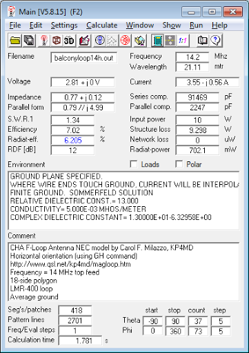
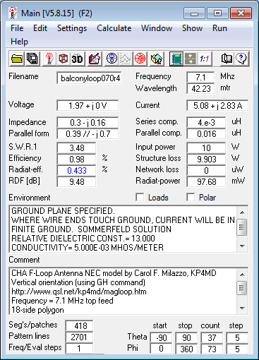
- Main screen (horizontal orientation);
- Main screen (vertical orientation);
- Azimuth radiation pattern for maximum gain in horizontal
orientation;
- Azimuth radiation pattern for maximum gain in vertical
orientation;
- Elevation radiation pattern;
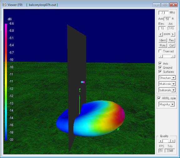
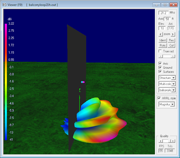
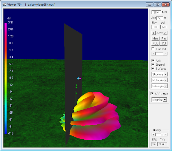
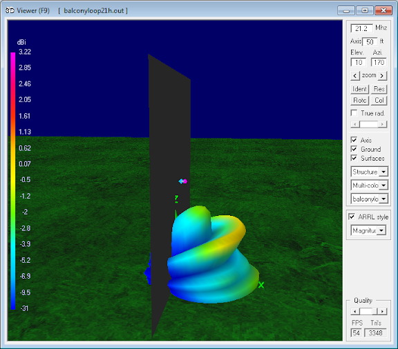
- 3 dimensional radiation pattern in horizontal orientation;
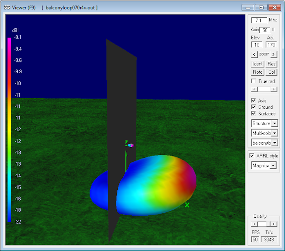
- 3 dimensional radiation pattern in vertical orientation.
In each of the two dimensional radiation patterns, the red
trace is for horizontal and the blue trace is for vertical
orientation.
0.5 to 2 Wavelengths Above Ground
7.1 MHz (0.5 λ) |
14.2 MHz (1 λ) |
21.2 MHz (1.5 λ) |
28.4 MHz (2 λ) |
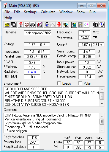
7.1 MHz Magnetic Loop Antenna Parameters - Horizontal
orientation
|
14.2 MHz Magnetic Loop Antenna Parameters - Horizontal
orientation
|
21.2 MHz Magnetic Loop Antenna Parameters - Horizontal
orientation
|
28.4 MHz Magnetic Loop Antenna Parameters - Horizontal
orientation
|
7.1 MHz Magnetic Loop Antenna Parameters - Vertical
orientation
|
14.2 MHz Magnetic Loop Antenna Parameters - Vertical
orientation
|
21.2 MHz Magnetic Loop Antenna Parameters - Vertical
orientation
|
28.4 MHz Magnetic Loop Antenna Parameters - Vertical
orientation
|
7.1 MHz Magnetic Loop Antenna - Azimuth radiation
pattern at 25� elevation
|
14.2 MHz Magnetic Loop Antenna - Azimuth radiation
pattern at 15� elevation
|
21.2 MHz Magnetic Loop Antenna - Azimuth radiation
pattern at 10� elevation
|
28.4 MHz Magnetic Loop Antenna - Azimuth radiation
pattern at 20� elevation
|
7.1 MHz Magnetic Loop Antenna - Azimuth radiation
pattern at 55� elevation
|
14.2 MHz Magnetic Loop Antenna - Azimuth radiation
pattern at 30� elevation
|
21.2 MHz Magnetic Loop Antenna - Azimuth radiation
pattern at 40� elevation
|
28.4 MHz Magnetic Loop Antenna - Azimuth radiation
pattern at 50� elevation
|
7.1 MHz Magnetic Loop Antenna - Elevation radiation
pattern
|
14.2 MHz Magnetic Loop Antenna - Elevation radiation
pattern
|
21.2 MHz Magnetic Loop Antenna - Elevation radiation
pattern
|
28.4 MHz Magnetic Loop Antenna - Elevation radiation
pattern
|
7.1 MHz Magnetic Loop Antenna Radiation Pattern -
Horizontal orientation
|
14.2 MHz Magnetic Loop Antenna Radiation Pattern -
Horizontal orientation
|
21.2 MHz Magnetic Loop Antenna Radiation Pattern -
Horizontal orientation
|
28.4 MHz Magnetic Loop Antenna Radiation Pattern -
Horizontal orientation
|
7.1 MHz Magnetic Loop Antenna Radiation Pattern -
Vertical orientation
|
14.2 MHz Magnetic Loop Antenna Radiation Pattern -
Vertical orientation
|
21.2 MHz Magnetic Loop Antenna Radiation Pattern -
Vertical orientation
|
28.4 MHz Magnetic Loop Antenna Radiation Pattern -
Vertical orientation
|
0.1 to 0.4 Wavelengths Above Ground
7.1 MHz (0.1 λ) |
7.1 MHz (0.2 λ) |
7.1 MHz (0.3 λ) |
7.1 MHz (0.4 λ) |
7.1 MHz Magnetic Loop Antenna Parameters - Horizontal
orientation at 4m (0.1 λ)
|
7.1 MHz Magnetic Loop Antenna Parameters - Horizontal
orientation at 8m (0.2 λ)
|
7.1 MHz Magnetic Loop Antenna Parameters - Horizontal
orientation at 12m (0.3 λ)
|
7.1 MHz Magnetic Loop Antenna Parameters - Horizontal
orientation at 16m (0.4 λ)
|
7.1 MHz Magnetic Loop Antenna Parameters - Vertical
orientation at 4m (0.1 λ)
|
7.1 MHz Magnetic Loop Antenna Parameters - Vertical
orientation at 8m (0.2 λ)
|
7.1 MHz Magnetic Loop Antenna Parameters - Vertical
orientation at 12m (0.3 λ)
|
7.1 MHz Magnetic Loop Antenna Parameters - Vertical
orientation at 16m (0.4 λ)
|
7.1 MHz Magnetic Loop Antenna at 4m (0.1 λ) - Azimuth
radiation pattern at 40� elevation
|
7.1 MHz Magnetic Loop Antenna at 8m (0.2 λ) - Azimuth
radiation pattern at 35� elevation
|
7.1 MHz Magnetic Loop Antenna at 12m (0.3 λ) - Azimuth
radiation pattern at 20� elevation
|
7.1 MHz Magnetic Loop Antenna at 16m (0.4 λ) - Azimuth
radiation pattern at 15� elevation
|
7.1 MHz Magnetic Loop Antenna at 4m (0.1 λ) - Azimuth
radiation pattern at 40� elevation
|
7.1 MHz Magnetic Loop Antenna at 8m (0.2 λ) - Azimuth
radiation pattern at 35� elevation
|
7.1 MHz Magnetic Loop Antenna at 12m (0.3 λ) - Azimuth
radiation pattern at 30� elevation
|
7.1 MHz Magnetic Loop Antenna at 16m (0.4 λ) - Azimuth
radiation pattern at 30� elevation
|
7.1 MHz Magnetic Loop Antenna at 4m (0.1 λ) - Elevation
radiation pattern
|
7.1 MHz Magnetic Loop Antenna at 8m (0.2 λ) - Elevation
radiation pattern
|
7.1 MHz Magnetic Loop Antenna at 12m (0.3 λ) - Elevation
radiation pattern
|
7.1 MHz Magnetic Loop Antenna at 16m (0.4 λ) - Elevation
radiation pattern
|
7.1 MHz Magnetic Loop Antenna Pattern - Horizontal
orientation at 4m (0.1 λ)
|
7.1 MHz Magnetic Loop Antenna Pattern - Horizontal
orientation at 8m (0.2 λ)
|
7.1 MHz Magnetic Loop Antenna Pattern - Horizontal
orientation at 12m (0.3 λ)
|
7.1 MHz Magnetic Loop Antenna Pattern - Horizontal
orientation at 16m (0.4 λ)
|
7.1 MHz Magnetic Loop Antenna Pattern - Vertical
orientation at 4m (0.1 λ)
|
7.1 MHz Magnetic Loop Antenna Pattern - Vertical
orientation at 8m (0.2 λ)
|
7.1 MHz Magnetic Loop Antenna Pattern - Vertical
orientation at 12m (0.3 λ)
|
7.1 MHz Magnetic Loop Antenna Pattern - Vertical
orientation at 16m (0.4 λ)
|
DISCUSSION
Predicted Antenna Parameters
Parameter |
Orientation |
7.1 MHz
@ 0.5 λ |
14.2 MHz
@ 1 λ |
21.2 MHz
@ 1.5 λ |
28.4 MHz
@ 2 λ |
|
Parameter |
Orientation |
7 MHz
@ 0.1 λ |
7 MHz
@ 0.2 λ |
7 MHz
@ 0.3 λ |
7 MHz
@ 0.4 λ |
Radiation efficiency |
Horizontal |
1.113% |
6.205% |
12.63% |
18.94% |
|
Radiation efficiency |
Horizontal |
0.216% |
0.608% |
1.04% |
1.12% |
Vertical |
0.695% |
4.352% |
8.972% |
13.67% |
|
Vertical |
0.85% |
0.484% |
0.9% |
0.433% |
Major lobe elevation |
Horizontal |
25� |
15� |
10� |
20� |
|
Major lobe elevation |
Horizontal |
40� |
35� |
30� |
30� |
Vertical |
55� |
30� |
40� |
50� |
|
Vertical |
40� |
35� |
20� |
15� |
Major lobe gain dB |
Horizontal |
-8.6 |
0 |
3.22 |
3.51 |
|
Major lobe gain dB |
Horizontal |
-17 |
-12 |
-10 |
-9.1 |
Vertical |
-11 |
-3.1 |
0.2 |
2.65 |
|
Vertical |
-11 |
-13 |
-14 |
-14 |
The models predict a uniformly higher radiation efficiency and
major lobe gain in the horizontal orientation for antenna
heights of 0.2 wavelengths and higher. The higher efficiency is
expected because in the vertical orientation half of the total
radiation is directed towards the ground and therefore subject
to ground absorption. At higher frequencies, the radiation
pattern exhibits increasing numbers of lobes and nulls. At
antenna heights of 0.5 wavelength and above, the horizontal
orientation uniformly yields lower angle maximum radiation lobes
that would favor long distance ionospheric propagation. At these
antenna heights, the vertical orientation yields higher angle
radiation lobes, offering a 7 dB signal increase over the
horizontal orientation at 55� elevation for short distance near
vertical incidence skywave (NVIS) propagation on 7 MHz.
CONCLUSIONS
This NEC model comparison suggests that the magnetic
loop antenna is preferably
oriented in the horizontal plane and at least 0.5 λ
above ground for long
distance ionospheric propagation and in the vertical
plane for short distance
NVIS propagation. In practice, the optimal
orientation of the antenna
will also depend on the polarization of local radio
noise and the height
above ground. The vertical orientation would
also be preferred
for operation through vertically polarized 28 MHz FM
repeaters.
REFERENCES
- 4nec2
Antenna Modeling Program, Voors, A
- Chameleon CHA F-Loop Antenna
Parameters, Milazzo, C, KP4MD
- Planar
Reflectors: Wire Grid vs. SM Patches, Cebik, L,
W4RNL
- A Universal HF Magnetic Loop
Model, Milazzo, C, KP4MD
PHOTO ALBUMS
- Balcony
Mounted Magnetic Loop Antenna, Milazzo, C, KP4MD
- Balcony
Rail Mount for Magnetic Loop Antenna, Milazzo,
C, KP4MD
- KP4MD/P
Amateur Radio Station in Puerto Rico, Milazzo,
C, KP4MD
|
NEC Model Parameters2
Height above ground |
69 feet (21.05 m)
|
Simulated ground type
|
Average
|
Loop diameter |
2.44 feet (0.74 m)
|
Loop circumference
|
92 inches (2.34 m)
|
Loop NEC model segments |
18
|
DXE-400 cable outer diameter
|
0.405 inches (10.3 mm)
|
Outer Jacket material
|
PVC |
Outer braid diameter
|
0.32 inches (8.13 mm)
|
DXE-400 braid conductivity
|
4500000 mhos/m
|
Capacitor Q=Xc/Rc* |
118-1800* |
*In switch position A: Rc = 0.032 + 5800/(FMHz�CpF�)
+ 0.0039�√FMHz
In switch position B: Rc = 2 � (5800/(FMHz�CpF�)
+ 0.0039�√FMHz) |
4nec2 Model Files
|