A dipole can operate on a second band by adding a third element.
The added element will shorten the dipole 10 to 20% and make antenna
rotation easier. The practical
range for the two bands is 6 meters to 15 meters… either as
neighbors such as 10 and 12 meters… or separated like 10 and 15
meters. This article discusses the principles of a two-band Tri-pole
antenna based on 6 and 10 meters. Instructions are given to build this
or any
Tri-pole antenna in the practical range.
First, about the three poles...
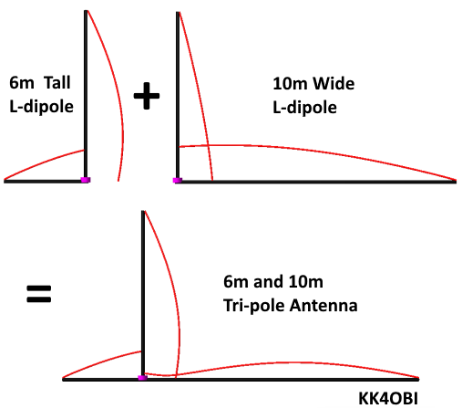
This antenna should be considered to be two L-dipoles with a common vertical element. Figure 1.
|
|
| Figure
1 Principles of operation |
Figure
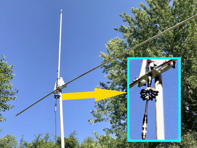
2 6 and 10 meter Tri-pole antenna with choke |
The antenna is fed off-center so a common mode choke must be used at the feed point for easier tuning and quieter operation. (Figure 2 insert) This isolates the antenna from the coaxial cable shield and prevents the shielding from becoming part of the antenna.
Vertical
The starting point of the design is to determine the frequency (length) of the vertical element. Curiously his frequency is not halfway between the desired upper and lower frequencies, but 0.47 between. In this case the two frequencies are 28.4 MHz in the middle of the 10 meter Technician band and 51.4 MHz near the middle of the 6 meter band.
Calculate the
vertical element frequency based on: f = 0.47 x (28.4 + 51.4) =
37.506 MHz
Using the usual
formulas where ft. = feet and f = frequency:
The starting dimension for the mid frequency quarter-wave vertical is: 6.239 ft. long.
Arms
Looking at Figure 1 it is apparent that the 10 meter horizontal arm is long and the 6 meter horizontal arm is short… too short and too long to be quarter-waves. The lengths depend on how far apart, in MHz, are the two frequencies. In this case the distance is at an extreme, 51.4 - 28.4 = 23 MHz between frequencies.
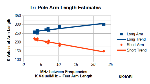
Looking at Graph 1 below you see the long and short trend lines relative to the MHz between Frequencies. To estimate Long and Short arm lengths apply the trend line K Values.
 |
| Graph
1 Trends for estimating Tri-pole arm dimensions |
At 23 MHz spacing, we see that the K Value for the Long Arm (blue) is
around 300.
Length (ft) =
K/f MHz = 300/28.4 MHz = 10.563 ft.
For the Short
Arm
(red) the K Value is around 150.
Length (ft) =
K/f MHz = 150/51.4 MHz = 2.918 ft.
We now have
starting dimensions for a 10m-6m Tri-pole
antenna.
Vertical
=
6.239 ft, 10m Arm = 10.563 ft, 6m Arm
= 2.918 ft.
Note the total horizontal length is 13.5 ft. which is 78% shorter than the 17.3 ft. of a 10 meter dipole.
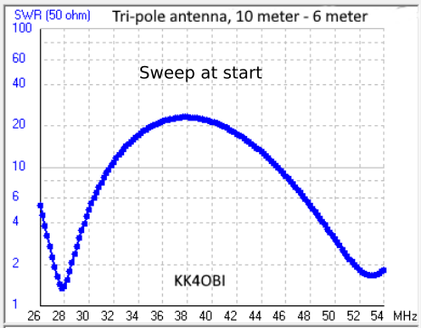
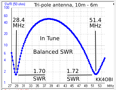
| Tuning and Balance Using these starting dimensions in a 4NEC2 computer model with #14 wire over Real Ground, a sweep (Graph 2) of this antenna at a half-wave elevation (17 feet) shows that we are close to the 28.4 and 51.4 frequencies. 27.8 MHz at 1.3
SWR. This can be improved. The long arm adjusts the 10 meter MHz. To raise the frequency from 27.8 to 28.4 MHz it was shortened from 10.563 to 10.513 feet. The short
arm
adjusts the 6 meter MHz. |
 |
|
|
Using these adjustments the new Tri-pole SWR values are 1.77 at 28.4 MHz versus 1.61 at 51.4 MHz. Still unbalanced. These can be brought into balance by adjusting the length of the Vertical element. |
Graph 2 Tri-pole sweep
using starting dimensions |
Rule for balancing Tri-pole SWR’s:
If the lower (left) frequency SWR is Higher, make the Vertical longer; or shorter if SWR is Lower.
In this
case the 28.4 MHz lower frequency SWR is Higher (1.77 vs.
1.61) so a balance is achieved by making the Vertical longer.
To keep the frequencies in tune, the both arms must be shortened to maintain the overall length. Note: this is tricky because both arms adjust the same direction contrary to the usual tuning methods.
The Vertical was lengthened from 6.239 to 6.34 feet. To fine tune this change the 28.4 MHz arm was shortened from 10.513 to 10.479 feet and the 51.4 MHz arm was shortened from 3.148 to 3.035 feet. The antenna model now indicates a good SWR balance of 1.7 and 1.72 at 28.4 and 51.4 MHz (Graph 3). This SWR is relatively high because the frequencies are relatively far apart. Frequencies that are closer together have lower SWR’s. |
 |
|
| We now have working dimensions for a 10m-6m Tri-pole antenna by use of wire antenna simulation. Vertical = 6.39 ft, 10m Arm = 10.479 ft, 6m Arm = 3.035 ft |
Graph 2 Tri-pole sweep
after tuning and balancing |
|
Construction: Wire vs Tube vs Whip
A two-band Tri-pole antenna can be made by modifying an existing vertical antenna having two radials or... by construction with wire or telescoping tubing or... for portability by using telescoping whips. Generally:
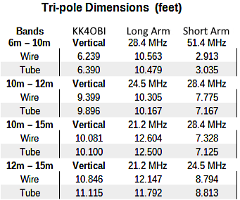
If tubing is used instead of wire, the vertical radiator will be longer
and the total horizontal length of the two arms will be shorter. Specifically: The
changes are very small between
the calculated wire dimensions and measured tube
dimensions of the antenna (Figure 2) as can be seen
in Table 1. The U-bolts used for mounting the antenna will add surface area to the vertical radiator and have a small affect
on tuning. |
 |
|
|
Table 1 |
Radiation Patterns
The 3D color pictures following are for total horizontal and vertical radiation fields. Thus the vertical component of a tall 6 meter L-antenna can skew the patterns to increase the signal level in a particular direction.
The radiation
patterns for the 10 and 6 meter Tri-pole antenna can be seen in
Figures 3 and 4 below.
The 3D color views are from looking down at a high angle relative to the antenna as shown.
 |
|
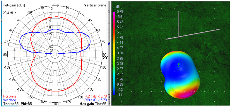
Figure 3
10
Meter radiation pattern at 17 feet (one ½ wave)
elevation
|
On the polar
graph in Figure 3 the half wave take-off angle is 25 degrees above
horizontal. (blue line, vertical plane)
Antenna gain is 5.78 dBi broadside to the arms with a -7.2 dBi null towards the short arm end.
The 3D color flyover view in Figure 3 shows a typical dipole pattern slightly skewed to the long arm side.
 |
|
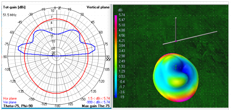
Figure 4 6 Meter radiation pattern at 17 feet (two ½ waves) elevation |
Gain is 5.74 dBi broadside to the arms and 1.5 dBi off the ends of the arms.
The 3D color flyover view shows an oval dipole pattern for the 15 degree lobe. This is favorable for DX contacts. The 50 degree lobe from the second half-wave is slightly skewed towards the short arm. This produces the high angle null as seen in dark blue.
Elevation Effects
At the ideal dipole elevation of ½ wave or higher, the RF reflected
from ground achieves maximum coupling with the ½ wave of the antenna to
give maximum radiation to produce increased signal strength. This (“ground gain”) produces the classic figure-8 pattern extending from the sides of a dipole antenna.
It can be seen at the ideal elevation of 17 ft. in both Figures 3 and 4 that the Tri-pole gain is about the same on either band, around 5.7 dBi. This gain can be compared to a standard dipole at 7.3 dBi, an L-dipole at 6.6 dBi or a standard vertical at 1.6 dBi.
If possible, mount any horizontal dipole higher than ¼ wave length because so much of the signal is lost skyward without the benefit of “ground gain”.
Construction Details
Materials List
|
Quantity |
Item |
Comment |
|
1 |
8-1/2” x 8-1/2” x 0.2-0.25” base |
Kitchen cutting board |
|
1 |
Closet Rod, 1-5/16” Dia., Wood |
Lengths from 6 to 12 ft. available for mast |
|
1 |
Tube 6 Ft x 1.00” OD, end slit |
Aluminum, 0.058” wall, for Vertical |
|
1 |
Tube 3 Ft x 0.875” OD, end slit |
Aluminum, 0.058” wall, for Vertical |
|
1 |
Tube 3 Ft x 0.75” OD, no slit |
Aluminum, 0.058” wall, for Vertical |
|
1 |
Tube 6 Ft x 0.75” OD, end slit |
Aluminum, 0.058” wall, for Long arm |
|
1 |
Tube 6 Ft x 0.675” OD, end slit |
Aluminum, 0.058” wall, for Long arm |
|
2 |
Tube 3 Ft x 0.50” OD, no slit |
Aluminum, 0.058” wall, for Long & Short arms |
|
1 |
Tube 3 Ft x 0.75” OD, end slit |
Aluminum, 0.058” wall, for Short arm |
|
1 |
Tube 3 Ft x 0.625” OD, end slit |
Aluminum, 0.058” wall, for Short arm |
|
1 |
Tube 3 Ft x 0.375” OD, no slit |
Aluminum, 0.058” wall, for Short arm |
Hardware List
|
Quantity |
Item |
Comment |
|
2 |
U-Bolt, 5/16” Dia x 1-3/8” U-ID x 2-1/2” L, Zinc |
Clamps for 1-5/16” Mast |
|
2 |
U-Bolt, 1/4” Dia x 1-1/8” U-ID x 2-1/4” L, Zinc |
Clamps for 1” Vertical |
|
2 |
SS Round Head Machine Screw #8 x 1-1/2”, washers, lock nuts |
Pivots for arms |
|
2 |
5/16” x 1-1/2” Clamping Knob, Star washers, Wing nuts |
Locks for arm angle |
|
1 |
Aluminum Angle, 1-1/2” x 1-1/2” x 3” for SO-239 |
Bridge connecting arms |
|
1 |
SO-239 Female coax connector, Panel Chassis Mount |
Mount with 4 screws |
|
1 |
Wood screw, #8 x 2”, Vertical radiator position lock |
Thru base to wood mast |
|
8 |
SS Hose Clamps, Size as needed for telescoping |
Vertical and arms |
 |
| Figure
5 Schematic Drawing |
 |
 |
|
|
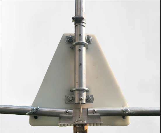
Figure 6 Tri-pole base, front view |
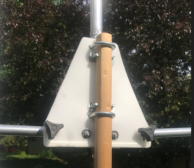
Figure 7 Tri-pole base, rear view |
The Base