Here is how it works. How to make one. How to use it.
Basics
Stainless steel telescoping antennas have been around a long time. The various versions have been touted for building collapsible, multi-band antennas. Of particular interest is the 17 foot model. From only 27” long, it can tune any band between 6 and the 20 meters as it is extended. And best of all, a pair of these eliminates radials by forming a half-wave antenna.
The easiest half-wave configuration (and the most compact) is to have one telescoping arm mounted vertically and the other arm pivoting to the side in an “L” shape. This is a bent dipole where the mixed radiation pattern is like a vertical but also has horizontal gain because of RF concentrated in the direction of the side arm.2
The problem is: How do you support a drooping telescopic antenna when it is up to 17 feet long?
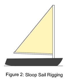
This where sail
rigging comes in. The vertical arm of the antenna is secured to a
mast. A line (halyard) runs up to the top of the mast, through an
eye and down to support the antenna side arm (boom).
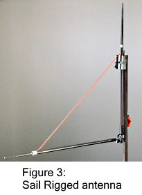
In this way the side arm is easily adjusted to any angle.
The halyard line is then secured to a cleat on the mast.
Tuning
Because the antenna is a half-wave, the total length of the two arms determines the frequency. The calculated length will be close to the desired frequency. Fine tuning is conveniently done by adjustments to the length of the side arm. It is not necessary to have the arms of equal length. However, a common code choke is advised, particularly if: (1) operating far from resonance, (2) feeding far from center,
Fine tuning also includes adjusting the Standing Wave Ratio, SWR.
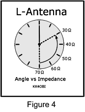 Generally the impedance of a straight resonant center-fed dipole is around 70
Ohms. Whether the dipole is horizontal or vertical makes little
difference.
Generally the impedance of a straight resonant center-fed dipole is around 70
Ohms. Whether the dipole is horizontal or vertical makes little
difference. If the lower half of a vertical dipole antenna is raised to a horizontal position, the impedance falls to roughly 35-40 Ohms. Somewhere in between there is the best match a 50 Ohm feed line.
Note that changing the angle also changes the frequency slightly. By alternately adjusting frequency and angle there can be found a point of minimum SWR or minimum reactance (antenna analyzer).
Tall and Wide Configurations to Tailor Characteristics
Because the telescoping arms can be different lengths, this makes it possible to emphasize vertical or horizontal characteristics of antenna radiation. This depends on frequency and height over ground.
If you cannot get the antenna very high, need a smaller antenna or want to talk to another vertical antenna, consider this: By lengthening the vertical arm there can be found a match for coax by shortening the side arm to maintain the total length for resonance. The taller the vertical arm, the more the antenna is like a vertical. About 75%/25% vertical/side half wave ratio is possible however the sweet-spot for best match is around a 60%/40% ratio. This is a Tall L-Antenna.3
Note: Signals will be noticeably stronger to and from the side with the side arm
If you can get the antenna up 1/3 to 1/2 wavelength high, this where the figure-8 directional gain of a horizontal dipole develops. To emphasize this horizontal gain characteristic, consider using a long side arm with a 60%/40% to 75%/25% side/vertical half wave ratio. This is a Wide L-Antenna.4
Note: a tall or wide configuration is not possible for 20 meters where both telescoping arms are already at maximum length.
Dipole Configurations give the best signal strength
If you can not get height, then you want the no-radial, low-angle, circular radiation of a vertical dipole. Merely point the side arm down. Take care to lead the feed line away as closely to horizontal as possible to minimize the coax coupling with the antenna. Tuning and SWR are affected because one end is closer to ground. Because of this, get as much clearance from the ground as possible. Fine tune by adjusting antenna length to get the desired frequency and by antenna angle for lowest SWR.
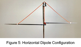
A horizontal dipole (Figure 5) is best.. If you can get the antenna feed point up approaching a 1/2 wavelength high, that is... around 9 ft at 6 meters, 17 ft. at 10 meters or 21 ft. at 15 meters. This is where the directional characteristics and full gain of a horizontal dipole work in your favor.
How to configure a horizontal dipole:
1. Use the sail rig to position the side arm horizontally and secure
the halyard to its cleat.
2. Release the vertical arm and halyard.
Pivot this arm to horizontal and secure the sail rig halyard to its
cleat. This forms a sideways L with the side arm pointing
forward.
3. Swivel the side arm to align the two arms into a horizontal dipole.
Take care to lead
the feed line down as closely to vertical as possible. A 90 degree
coax connector is desirable. Adjust antenna length for the desired
frequency. A 1:4 SWR is very good for a horizontal dipole.
Droop has no detectable effect and is compensated by the sail rig. As usual, angle adjusts SWR.
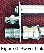 A swivel link (Figure 6) between the two telescoping whips is the key
detail. This link is made from 1-1/2” x 1-1/2” x 1/8” thick Aluminum Angle stock. Use two sections 1-1/8” wide.
A swivel link (Figure 6) between the two telescoping whips is the key
detail. This link is made from 1-1/2” x 1-1/2” x 1/8” thick Aluminum Angle stock. Use two sections 1-1/8” wide.
As can be seen, the swivel side is shortened to 1” and rounded. Connection is by a #10 x 1/2” Stainless Steel (SS) machine screw, washers(2) and lock nut. Spacing between whips is 1-3/4” on centers.
The upper whip connection uses a 3/8” x 24 nut and washer.
The lower whip
connection uses a SO-239 to 3/8” x 24 Threaded Stud antenna
mount adapter.
The antennas are connected to the mast by the stud
mount adapter using a #0 ACC conduit and pipe hanger pivot (figure 8). A 3/8” x 1”
washer is used (as shown) between this adapter and the whip to prevent slippage
when the antennas are clamped in the pipe hanger pivot.
Be sure that there is whip continuity between the stud mount adapter and the center pin of the coax connector… and that there is no connection to the other whip.
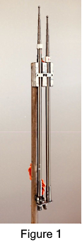
A holder block on the top of the
mast secures the whips when not deployed (Figure 1).
The holder is made from a 3” x 3” x ½” wood base and (2) ½” x 5/8” x 3” side strips and a 7/8” x 5/8” x 3” center strip.
The lock-hooks are from ½” x ½” aluminum angle pieces 1-1/2” long (2). The vertical edge is removed except for a ½” section at the hook end which provides a lifting tab.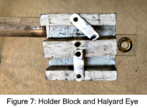
It is left to the builders’ ingenuity on how to attach the block to the mast inline with the coax-fed whip.
The final parts of the sail rig mast are the cleats for the lines and the pivot to make a horizontal dipole.
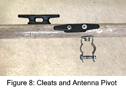
To attach the two whips, the Threaded Stud Antenna Mount adapter of the antenna assembly is placed in the Pipe Hanger. The two whips are aligned with the holder block. The Pipe hanger is tightened securely on the Threaded stud
The 3” nylon cleats are mounted as shown.
Final assembly: Rig the sail.
The side arm swings from up to down. To do this requires 84” (7’) of line. The vertical arm pivots only horizontally to form a dipole. It needs only 70” (5’ 10”) of line.
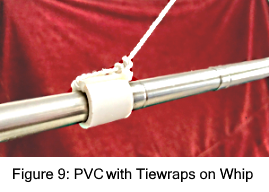 Each line is tied to a ½” section of ½” PVC pipe. This pipe
piece is used to attach the lines to the telescoping whips.
Each line is tied to a ½” section of ½” PVC pipe. This pipe
piece is used to attach the lines to the telescoping whips.
Two 4” cable ties are looped through the pipe piece. These will reduce the internal diameter so that the pipe stops at the end of the second telescoping section at 38”.
The bitter-end of the line goes up through the grommet eye and down to a cleat on the mast to complete the rigging.
The pole or tube can be supported by a house, vehicle, table, fence, balcony rail or a tripod secured to the ground. Whatever the situation you will want to be able to reach (ladder, table) the halyard and cleats on the mast and be able adjust the length and angle of the side arm while looking at your antenna analyzer. Fine tuning at a lower level then raising the antenna will lead to many up-down cycles because tuning changes with height.
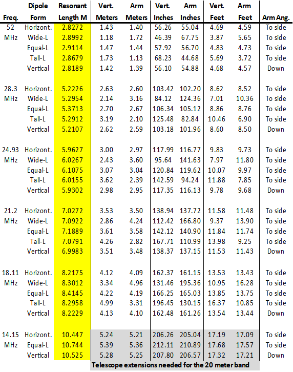
Sail Rigged Utility Antenna
Dimensions for the 6, 10, 12, 15, 17, and 20 meter bands
Based on feed point elevation of 20 feet (6 Meters)
Vertical-to-Arm ratios are: Wide-L = 40/60, Equal-L = 50/50, Tall-L = 60/40
(Go Back)
============================================================================