
"End Effect" on an End-Fed-Half-Wave Antenna
This article presents the findings of an antenna
modeling study of the changes in harmonics produced by feeding a half
wave antenna near one end. The data reveals where the harmonics
are best alignened and quantifies the end effect at that feed
point. Considerations about installing this type of antenna are
presented based on the study results.
The way amateur radio handles end effect is to include compensation in
the 492 value used the antenna formula 492/MHz x K= feet, where K
adjusts for velocity, wire size, insulation or tubing
diameter. This served well for the past 100 years but the
rise of interest in end-fed (or more accurately) near-end-fed half-wave
antennas raises a problem.
In principle these antennas resonate on the 1st, 2nd, 3rd… thru 8th
harmonic. Well, almost. The problem is that the end effect
really involves only the 1st harmonic and a little bit on the 2nd
harmonic. There is practically no effect beyond that so the
higher harmonics are not true multiples of the short 1st harmonic.
The radiation pattern does not change. The only change is impedance and harmonics.
The question then is “At what feed point ratio do the harmonics line up best”.
The Study
To answer the question, 3.6 MHz was selected as the fundamental frequency or 1st harmonic. This was multiplied by 2, 3… 8 make the harmonic set. Using an antenna model standardized at ½ wavelength feed point elevation and #14 copper wire over “real ground”, each frequency in each set of harmonics was optimized for its‘ resonant length in meters. No two lenghts were the same.
This process was repeated for six feed point ratios set at 0.90, 0.91, 0.92 … 0.95 of the 3.6 MHz half wave. Each ratio produced a different set of resonant lengths for each harmonic as seen in Figure 1.
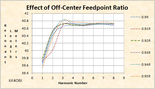
Figure 1
It is obvious that the 1st harmonic is about 1 meter shorter than the higher harmonics. This is the end effect.
It is also obvious that the harmonics 3 thru 8 are little affected and can be alined to have minimal variation.
Where do harmonics line up the best?
For the six feed point ratios from 0.90 to
0.95, the mean, standard deviation and min-max variance was determined
for the 80, 40, 30, 20, 17, 15, 12 and 10 meter sets of
harmonics.
As can be seen by the” Relative Change” in
Figure 2, that the harmonics are best alined using the 0.92
ratio. That is to say when a 3.6 MHz half wave wire antenna is
fed 8% or 10.7 feet from the end.
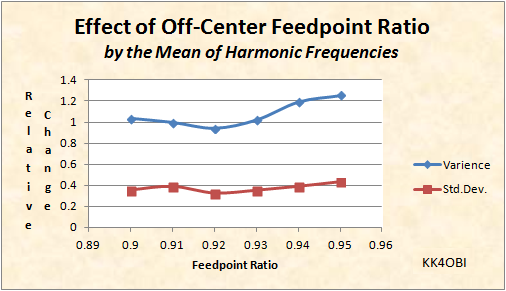
Figure 2
|
End effect is only on the ends. That is not as simple as it sounds when you are dealing with harmonics. |
- On the second harmonic the 80 meter wire divides into two 40 meter half waves… four ends. That means only the outer two ends have the end effect.
- On the third harmonic the wire divides into three 30 meter thirds… six ends. Only the outer two of six have end effect.
- On the forth harmonic there are four 20 meter half waves… eight ends. Only two of eight have end effect.
- And so it continues
through the 8th harmonic with little effect.
·
How big is the end effect?
The end effect on the 40 meter second harmonic is smaller; a total of 6.45 inches short or 3.23 inches on each end. End effects on the remaining higher harmonics are small and can be neglected.
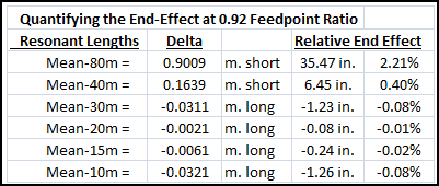
Table 1
Thoughts about installing an End-Fed-Half-Wave antenna.
For tuning, the usual method of trimming a wire antenna to the desired frequency is frustrating. Any change in one band changes all bands. If you tune the first harmonic (80 m.), the second (40 m.) will be off and the higher harmonics practically useless. If you tune to the higher harmonics (20 meters for example), 80 m. will be useless.
Clever amateur radio operators have devised ways to switch in extra length or inductance to solve the problem. More recently commercial End-Fed-Half-Wave antennas have a small inductor about six feet from the feed point. This and a small capacitor in the transformer case shifts the higher harmonics to be in line with the fundamental frequency.
How the antenna is deployed will affect tuning. If the harmonics are slightly high in frequency the antenna can be lengthened slightly. A wire stub or small telescoping antenna attached at the transformer can be employed. Anything over a foot (12”) in length or so will start to have undesirable results. A long wire or radial is inappropriate and should not be considered.
If the harmonics are slightly low the antenna can be slightly shortened. Before cutting, a temporary shortening can be tried by passing a loop of the antenna wire through a small ferrite toroid. This essentially shortens the antenna by the length of the loop.
Common mode
currents occur from off-center feed and off resonance operation. To keep RF out of your operating site a choke
is advised. A
choke at the antenna transformer is not advised. It cuts off the
part of the antenna that the coax provides. Recall that the best
feed
point in the study was 8% from the end. This suggests inserting
the choke in the coax line10.7 feet or more
from the feed point of a commercial 80 meter End-Fed antenna. In
practice a choke placed at the entrance to the operating site is
preferred if noise pickup on the coax is not a problem.