DSP* SPEAKER SYSTEM
Pete Wokoun Sr, KH6GRT
November, 2015
*Digital Signal Processing
This project originated a couple years back when I read Allen Baker KG4JJH's article BUILD YOUR OWN DSP SPEAKER that appeared in the November, 2011 issue of QST. It's a great comprehensive article and you can view a .pdf of it by clicking HERE. Allen's dsp speaker used a BHI-LTD audio noise reduction unit with an amplified speaker. I used a BHI-LTD HEAR IT IN-LINE MODULE for several years and was familiar with and impressed with its noise reduction capabilities. That in-line module goes between the radio and speaker; however, I liked the idea of everything in a single package. I used Allen's dsp speaker as a starting point and modified it to suit my requirements. I started gathering parts a year ago and got serious about putting it together 3 months ago.
I generally used Allen's circuit except for his rotary DSP LEVEL switch and diode binary converter. I used a binary DSP LEVEL selector switch to control the noise reduction module directly, added a second clipping detector to monitor the audio circuits, and added adjustable low- and high-frequency audio filters.
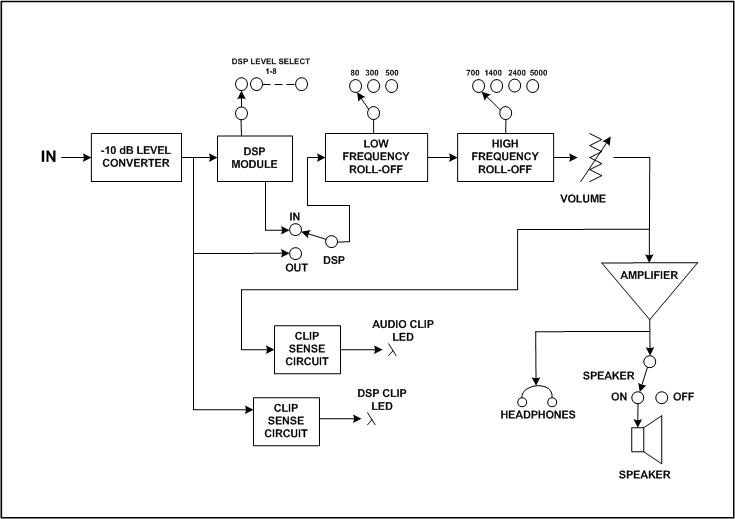
Here's a block diagram of my dsp speaker system:
The clip sense circuits are designed around a window comparator. They enable you to monitor an AC signal that lets you know when the level is at a predetermined level. The DSP CLIP LED is adjusted to mimic a LED on the DSP module board. These LEDs light when the DSP module input reaches the overload level. The AUDIO CLIP LED is adjusted to light when the signal to the speaker just starts to clip letting you know you're getting more distortion products. The clip sense circuit was obtained from the internet at www.redcircuits.com/Page132.htm.
H. Ward Silver N0AX in his HANDS-ON RADIO column in the October, 2014 QST had a good description of how a window comparator works. You can see a .pdf of that column HERE.
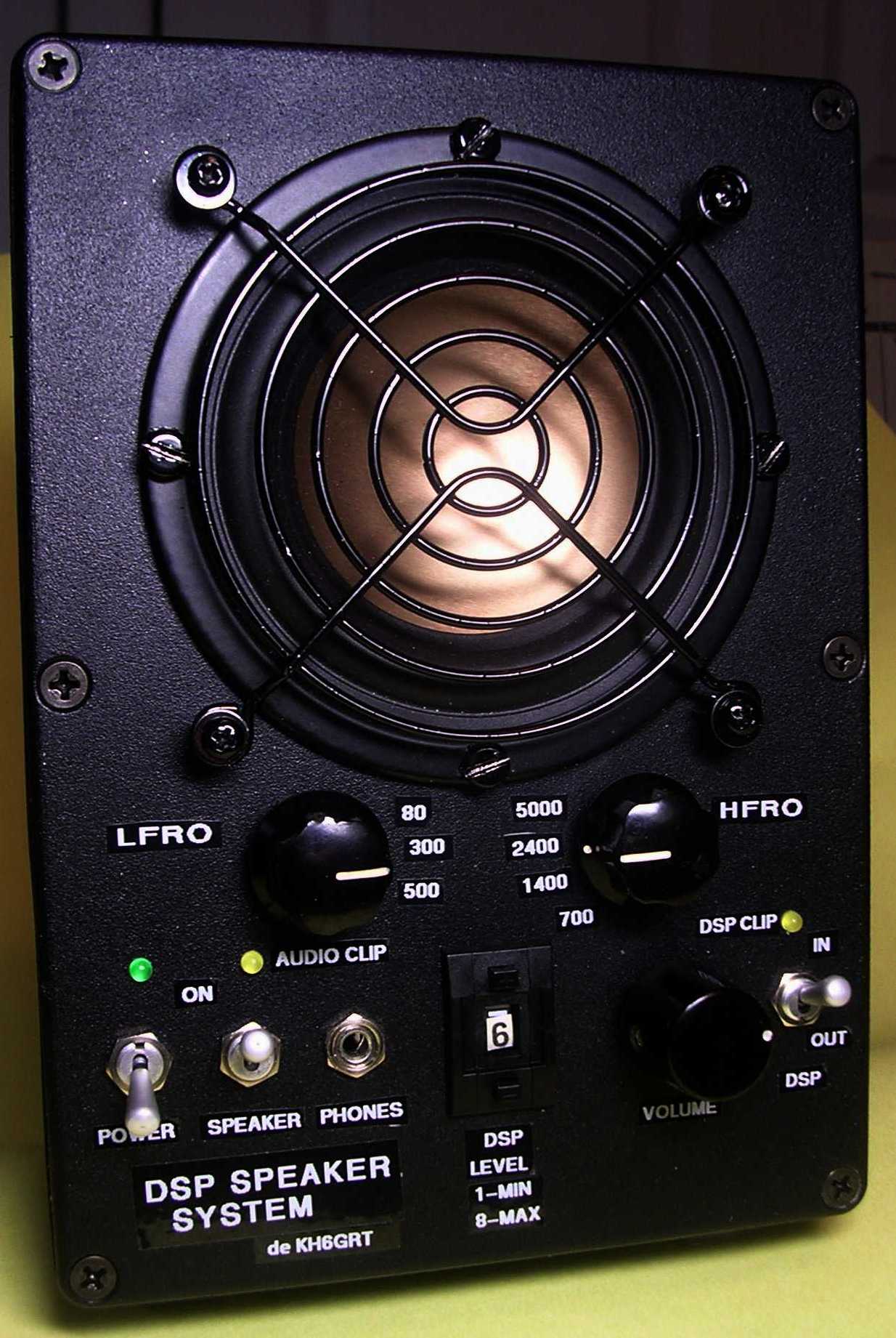
Here's a front panel view of my speaker. Click on the picture for a larger view; use your back arrow to return here. The total height is about 7 inches, the width is 4-3/4 inches and the depth is 5 inches.
I think using an aluminum enclosure rather than plastic really helps to prevent RF feedback problems. Ferrite beads are used on all jacks where leads could introduce signals from outside the enclosure. No feedback is heard from this speaker even when using a high power transmitter.
The enclosure is sealed which results in a very tightly coupled speaker. Subjectively, this results in a surprisingly nice response from such a small 3 inch speaker although more power is required to drive it. Front panel and speaker gaskets are used to seal the enclosure and prevent rattles. The enclosure walls are lined with 1/2-inch acoustic foam. The only air leaks are from from the small 1/8-inch headphone jacks but they don't seem serious.
One result of having a lot of time between the thought of a project and the actual implementation is the tendency to keep adding to it and deviating from the original concept. Not that this is a bad thing, it gives you time to make it 'yours'. The low- and high-frequency roll off adjustments were just that. I've seen commercial speakers with this feature and wondered how much it really helped. That's when I decided to include it and see. I did some testing on the roll off responses and this is how they turned out:
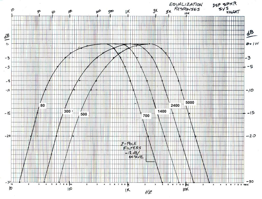
All in all, the corner frequencies appear nicely spaced.
The filtering might make a difference during contesting or weak signal communications but I don't think much during arm-chair copy.
Throughout this discussion the low- and high-frequency roll off filters will be referred to as the LFRO and HFRO filters, respectively.
Let's look at the construction of this speaker:
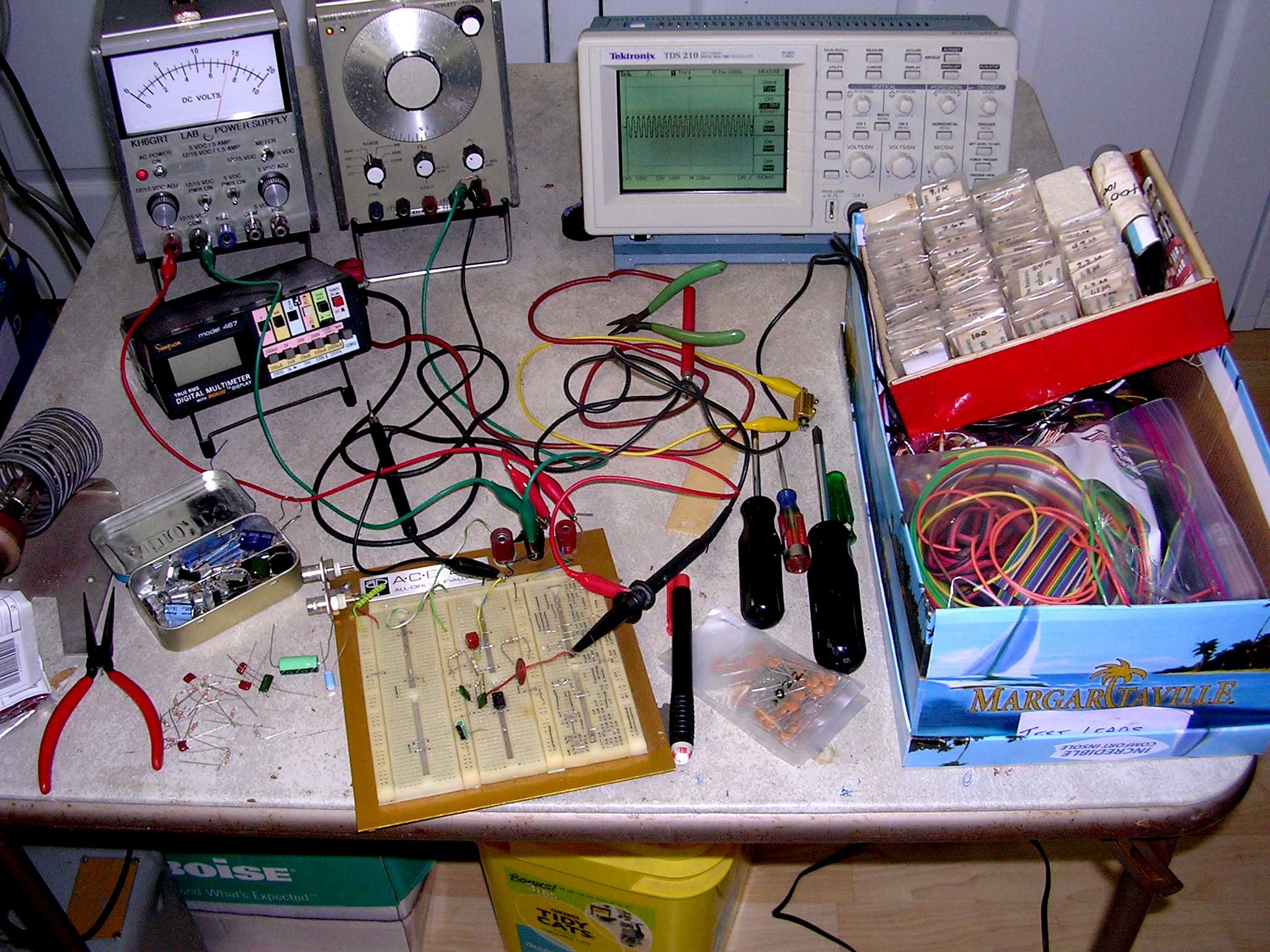
This was my 'play table' where I breadboarded and checked out the circuits before building them. Eventually the whole speaker was built here.
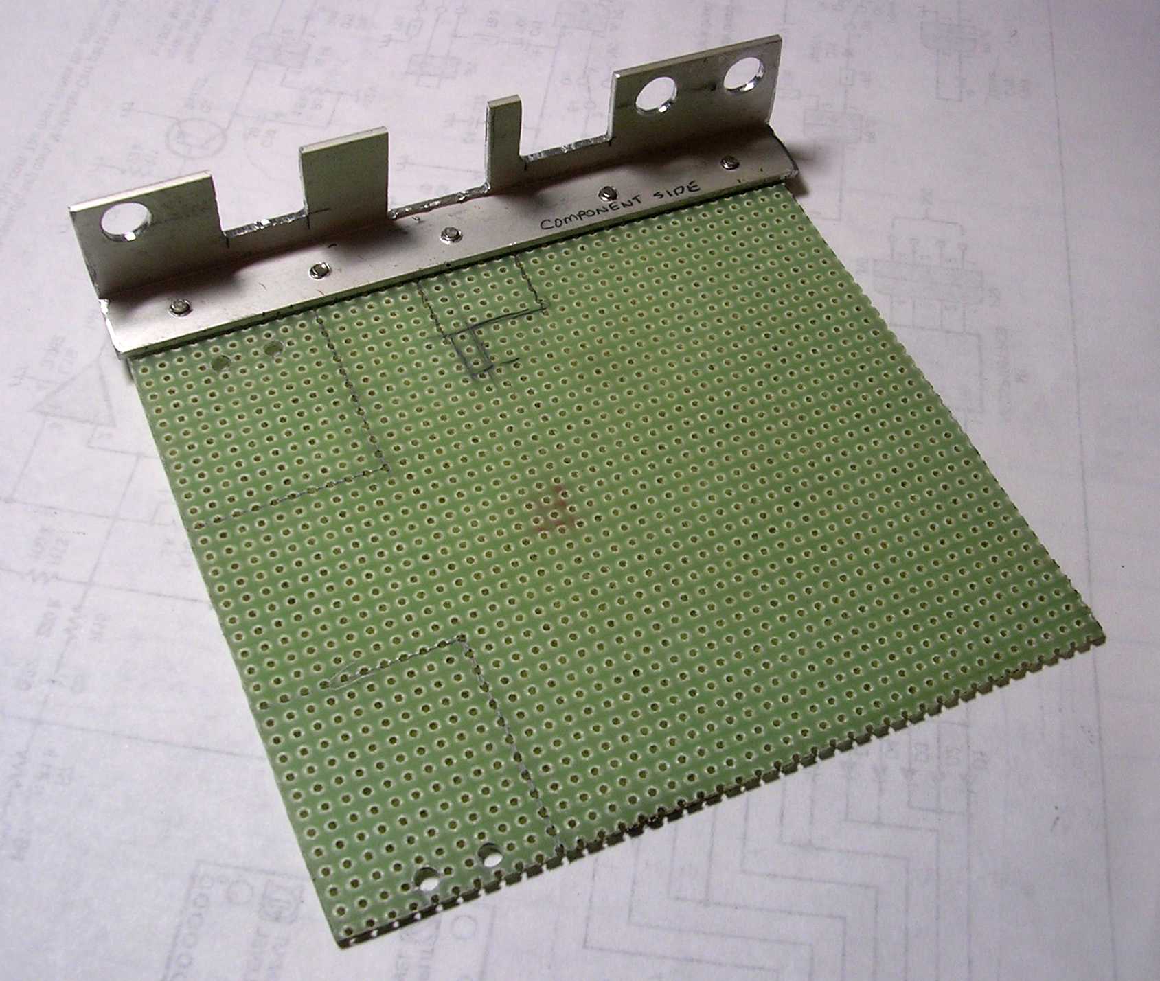
This is the glass epoxy perfboard used to hold the components. It has a grid of 0.042" holes spaced 0.1" from each other. The aluminum angle is used to mount the board to the front panel. It is held to the front panel by the three toggle switches mounted through the round holes. The cutouts are for the volume control, the DSP LEVEL selector switch, and the earphone jack. These did not have threaded barrels long enough to go through both the front panel and the aluminum angle. Penciled in are interferrence areas where I didn't want to install components.
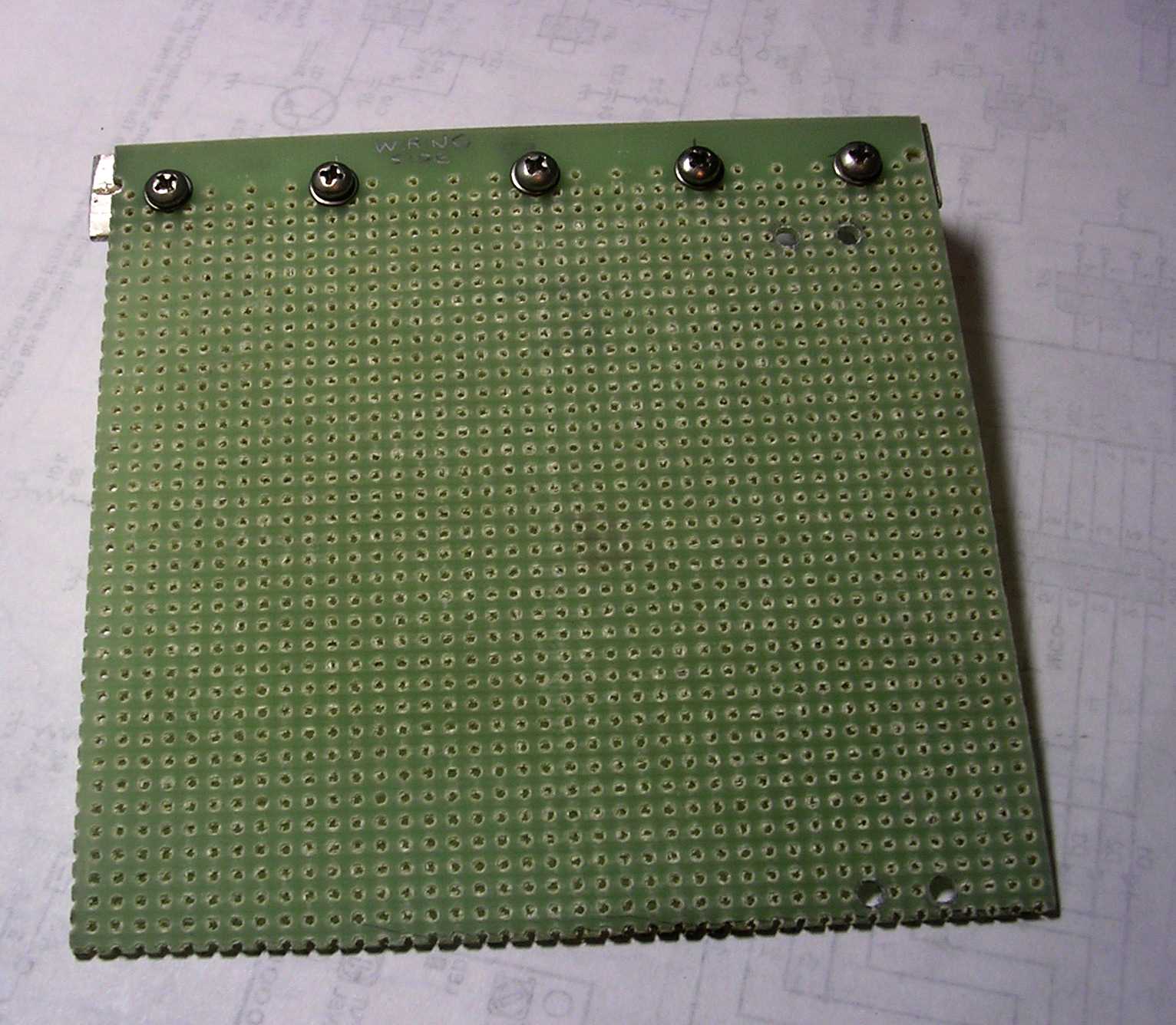
Bottom-side view of the board before anything mounted.
I use Vector pins for a lot of my prototyping and construction to hold the components. For this board I used their T44 multiwrap pins for the components and R32 socket pins for the ICs and transistors. These pins are designed for wirewrap tooling which I don't have anymore. You also need the proper insertion tools for the pins to seat good. I cut off about 2/3 of each pin before doing the point-to-point wiring. If any more of the pin is left after the wiring, I cut that off too.
Prior to wiring I draw up a 'road map' on a piece of grid paper showing all the components from this back side. I sketch in the wiring showing where all my point to point interconnects are going to go. Without doing this it can be very confusing and tiring wiring on this side while viewing the components on the other side, back and forth, back and forth, etc.
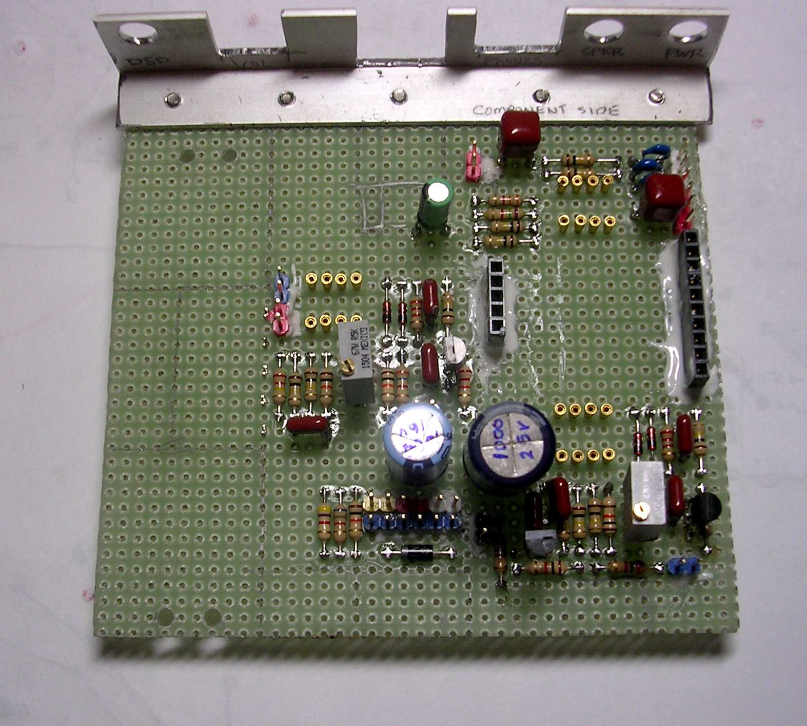
Here's the top of the board with components soldered to the Vector pins. You definitely need a small pencil tip on your iron for soldering this stuff. I solder the components before doing any wiring on the backside; it helps hold the pins in place. I found the headers and connection pins needed a little epoxy to hold them in place.
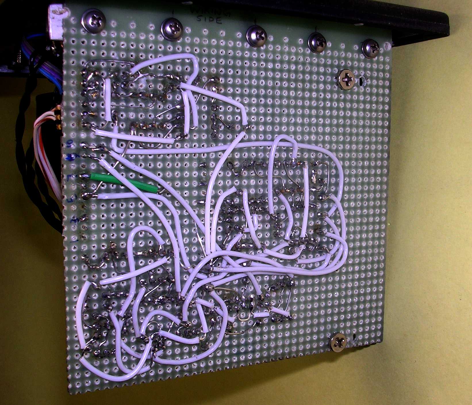
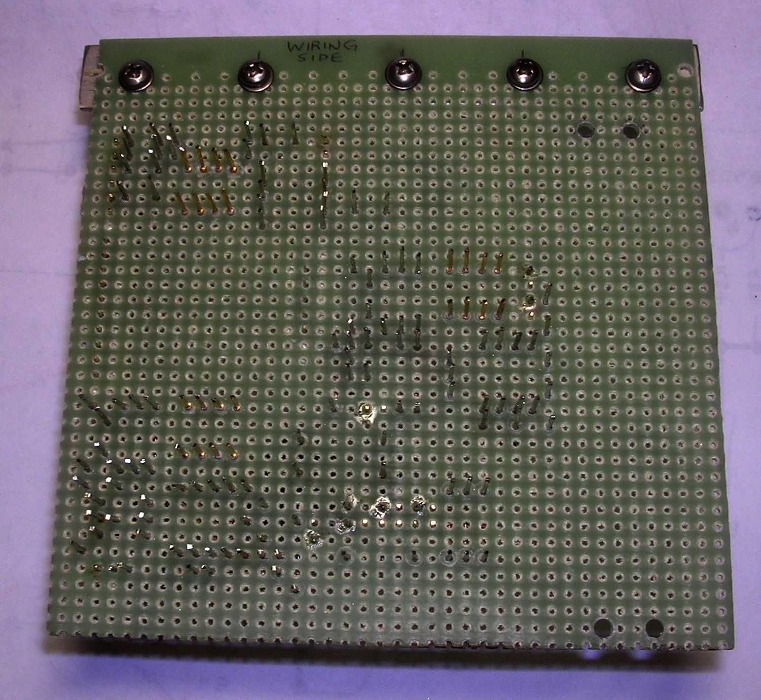
Here's all the point-to-point wiring on the bottom side of the board. I usually use #22 bare tinned copper wiring for all this stuff. This is stiff enough so that if you form it around the pins and squeeze it with a pair of needle pliers it remains holding the pins. I first wire all the interconnects that don't need insulating tubing, then go do the ones that need it.
A nice source for bare wire is to get a foot or two of #12 or #10 teflon insulated stranded wire. Strip the insulation off with a razor blade or knife and you end up with nice silver plated wire that solders beautifully. A spool of the teflon insulation is also a must.
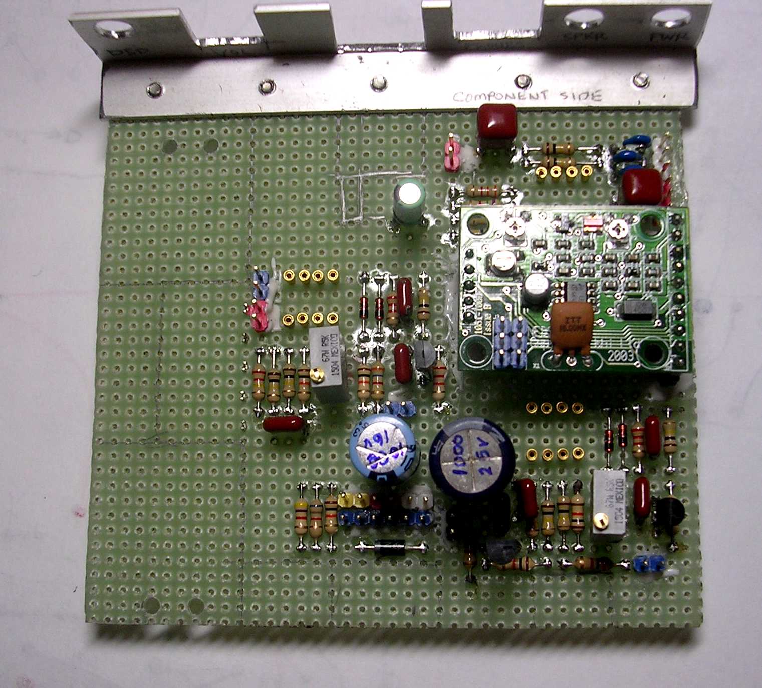
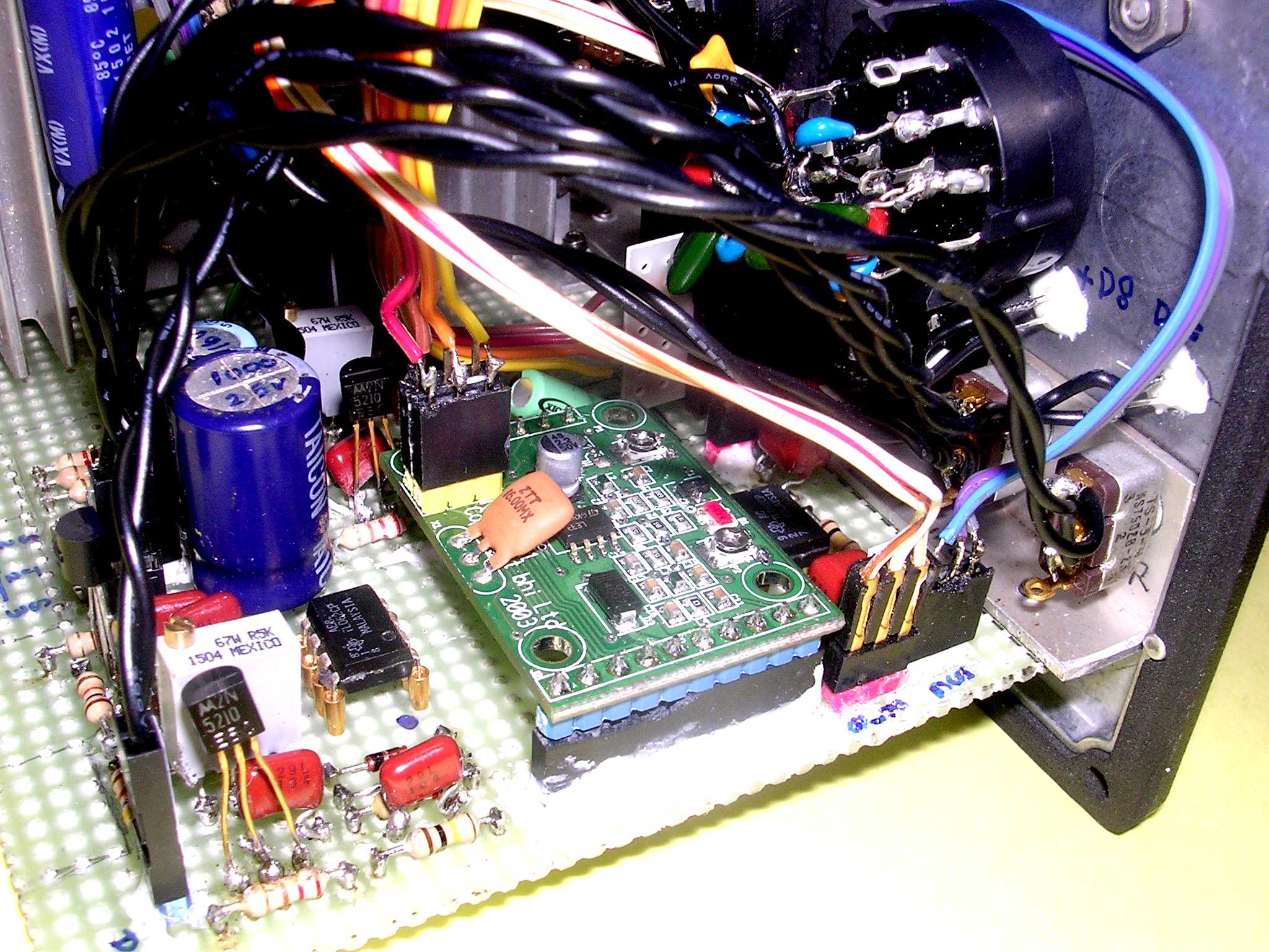
Component side of board with DSP module installed.
The correct BHI module you want for this type of application is the NEDSP1061-PCB, NOT the NEDSP1061-KBD. The -KBD version is designed for insertion into a transceiver and won't work here.
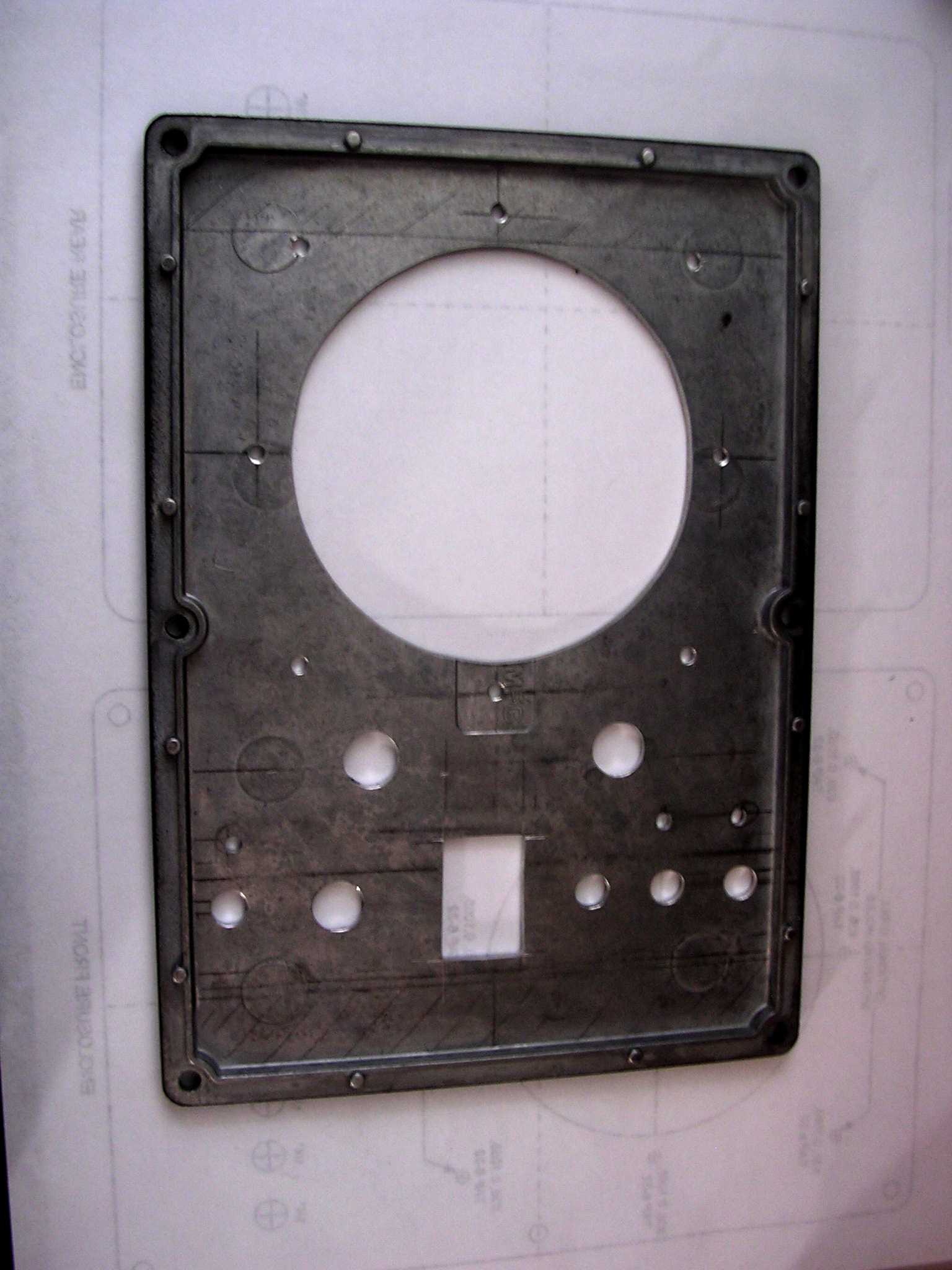
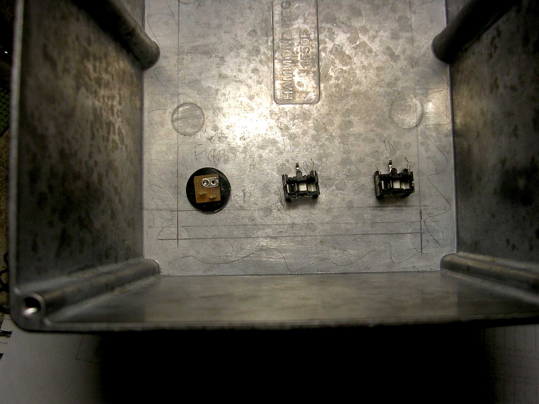
Inside front cover after holes were drilled.
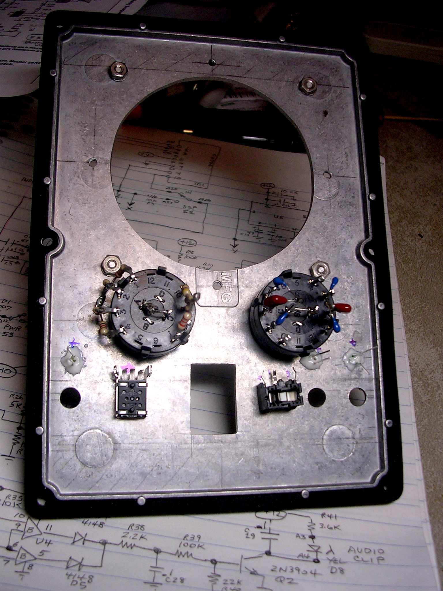
Inside front cover after holes were drilled and some parts were installed. The roll-off switches were pre-wired.
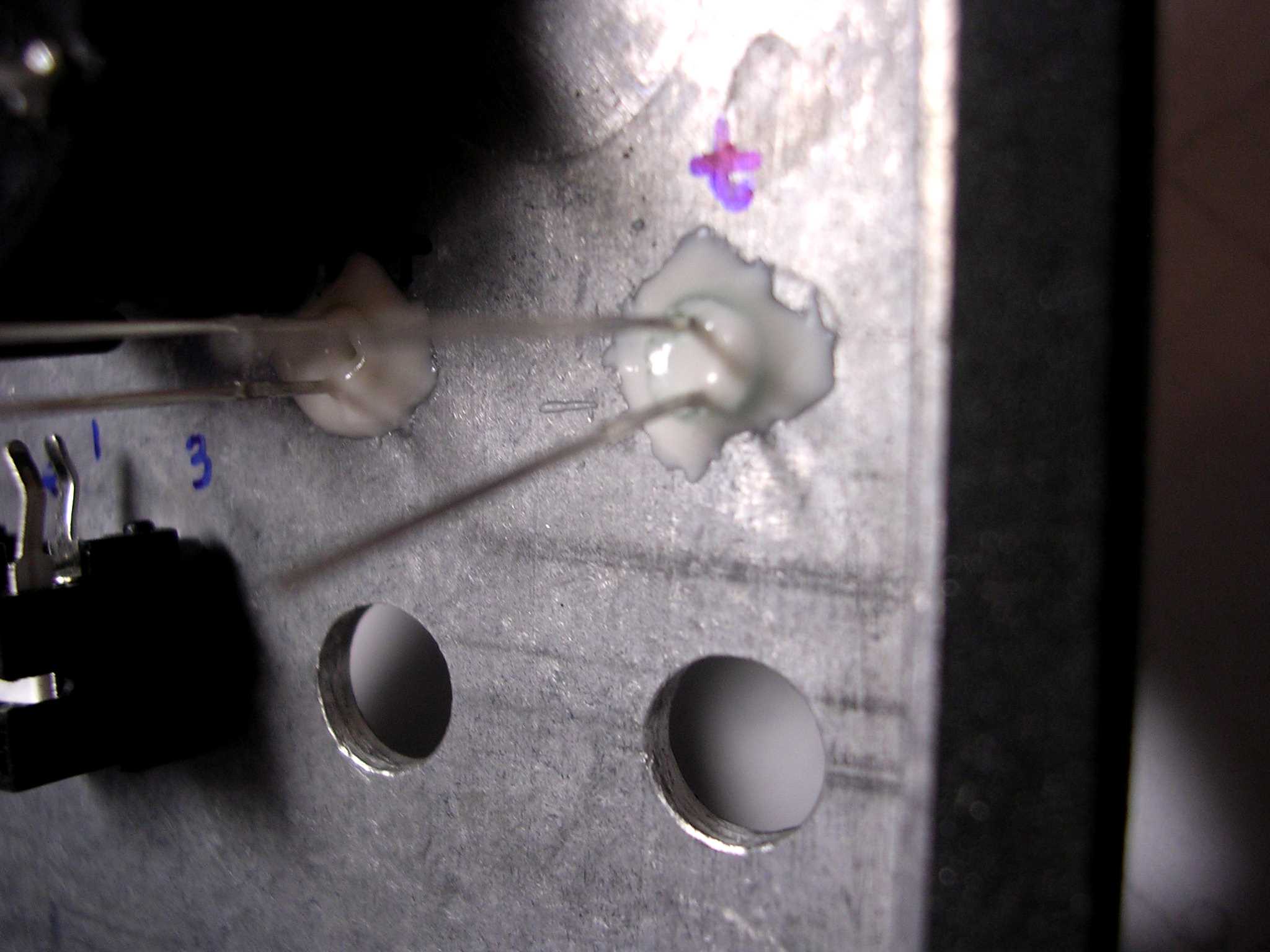
I can usually install LEDs into a nice tight press fit hole because they have a slight taper. But not here....I had to epoxy them to keep from falling out. These LEDs are the small T-1 size.
Inside the rear enclosure. One of my oops moments, that input jack on the right interferred with the heatsink and I had to slide it over to the left a little.
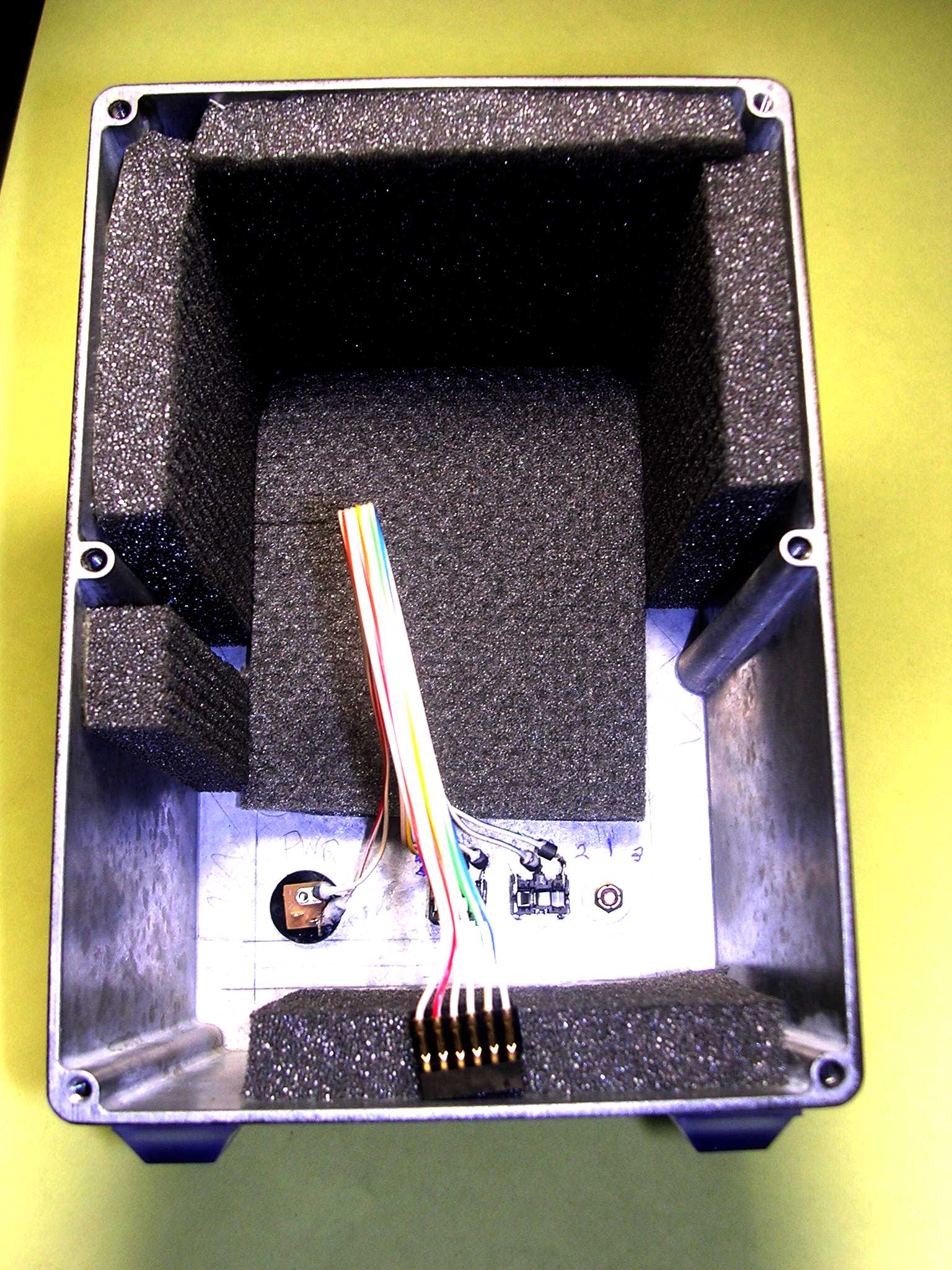
Acoustic foam installed inside the enclosure. The heatsink is located next to the right side panel so no foam was installed there. Note the ferrite beads on all the leads by the jacks. Adhesive was put on the beads to prevent rattles as suggested by Allen.
Completed inside of the DSP SPEAKER SYSTEM. The amplifier was wired on the heatsink and everything else on the perfboard. This was done so I could try different amplifiers and easily change them. That heatsink is a custom item; it happened to be in my junque box and I used it. With a little more thought I could have rearranged all those jumper wires but no problems appeared. I just like things neater.
I also didn't use any shielded wire in here. I was a little apprehensive about having hum problems. But everything turned out very quiet, no problems at all.
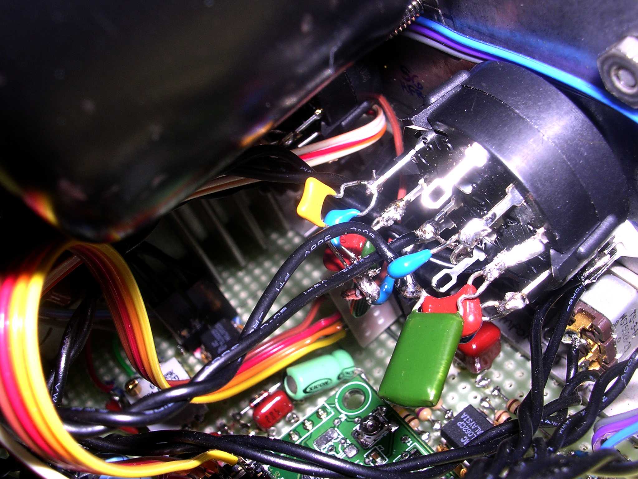
Another view of the inside board centered on the DSP module.
Another inside view looking at the LFRO selector switch. Things got a little tight in there!
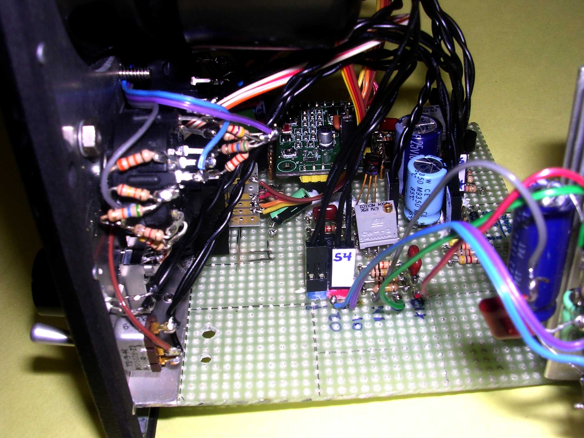
Another inside view of the HFRO switch with the amplifier heatsink rotated out of the way.
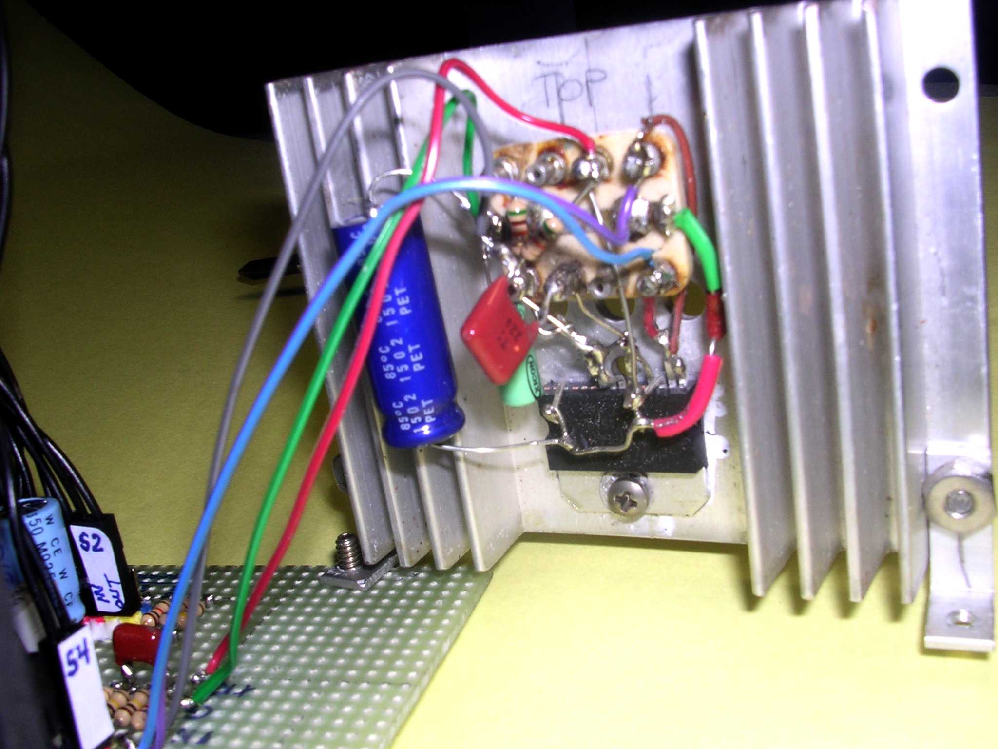
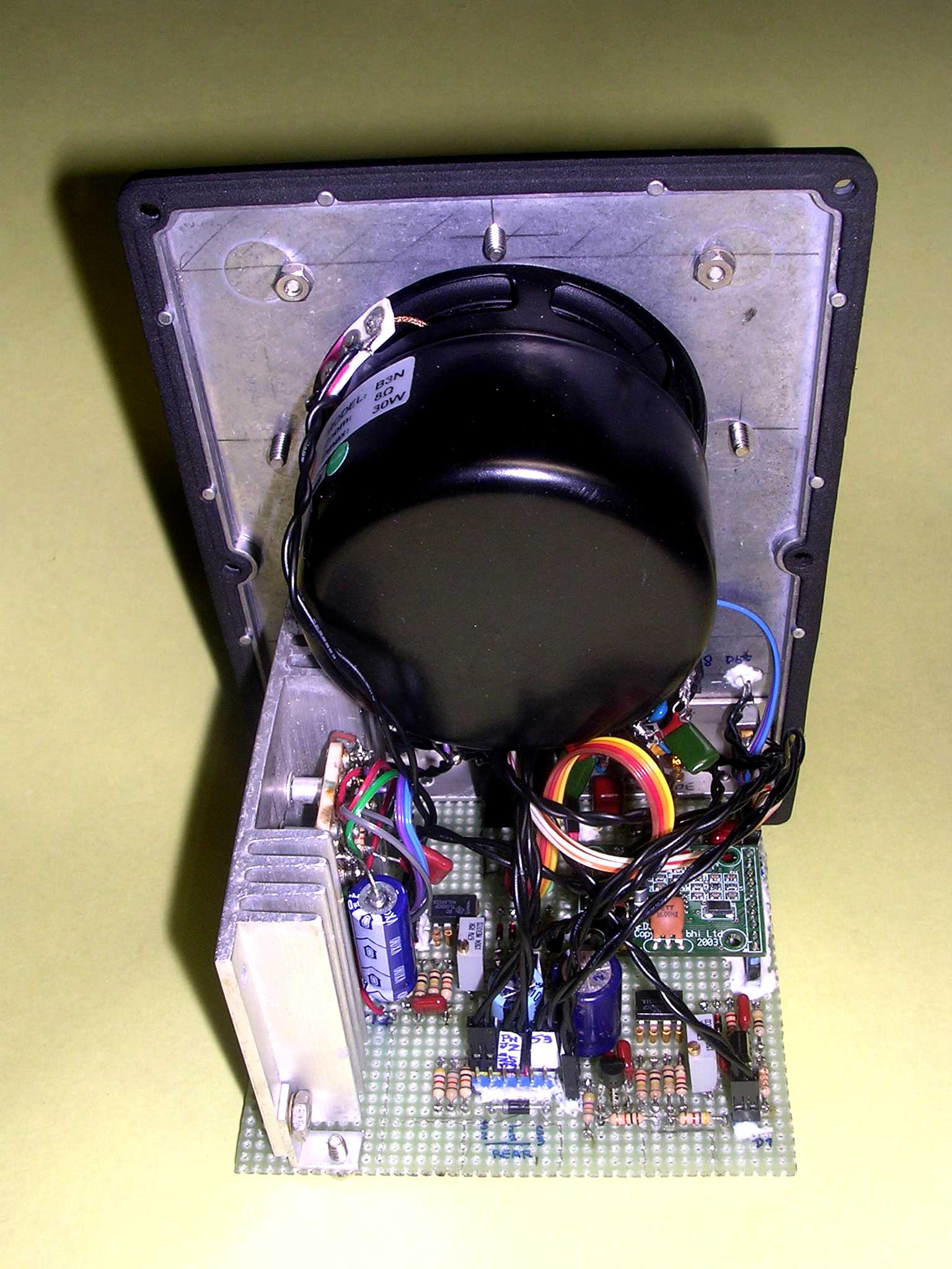
View of the amplifier heatsink rotated out of the way on its rear mounting screw. This method lets me remove the amplifier easily to try other ones.
This one is using the TDA7266M chip. I also tried the TDA7240A chip. Both put out about 8 watts at the onset of clipping but I liked the 7240 one a little better because it had 14 dB more gain.
The TDA7240A chip is now obsolete and you can't get it from the big supply houses but you can still find them on eBay.
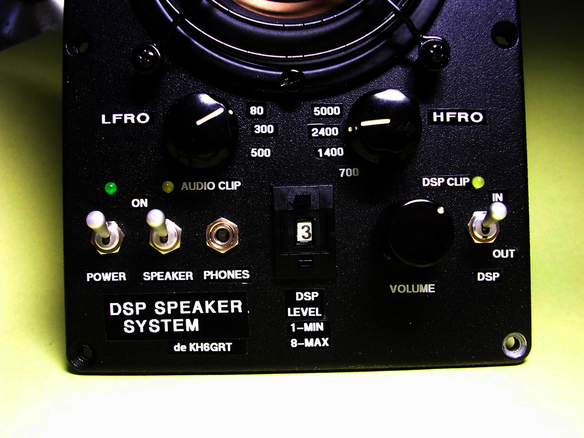
Close up of labels on the front panel. I used Brother P-touch labels, white on black tape.

![]()
![]()