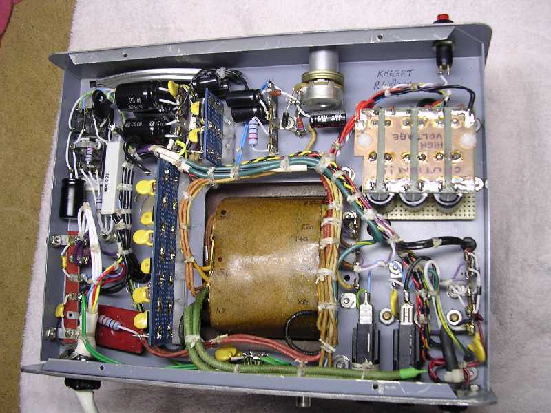
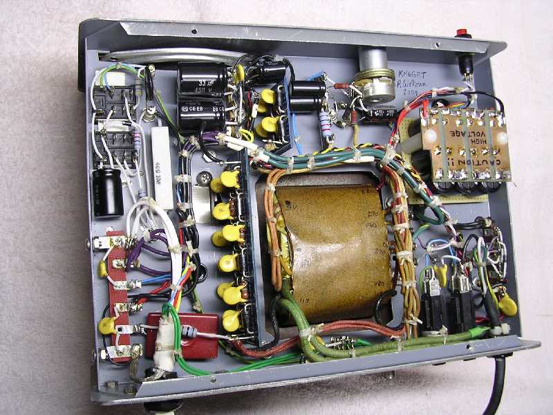
THE 516F-2 PROJECT
P. Wokoun, KH6GRT (1/2004)
This is result of my attempt to produce an AC power supply equivalent
to a Collins 516F-2 less expensively than I could buy one.
The need for a power supply became apparent by my working on Collins 32S3 transmitters
and KWM2 transceivers. I would always have to make sure their power supplies
came with them which meant hauling around lots of weight. I also recently acquired
my own 32S3 and now needed a power supply for it.
Attemps to obtain one from e-bay at what I considered a reasonable price proved
futile. Prices seemed to stay above $250 which seemed a little high considering
the prices some transmitters sold for.
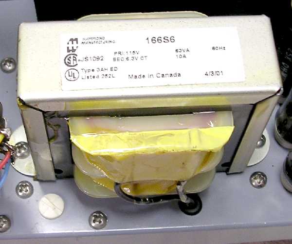
I had a replacement transformer for the Hallicrafters HT-32/37 series of transmitters.
Both the Collins and Hallicrafters use a pair of 6146s so I reasoned the power
transformers should be somewhat similar. I also had an LMB cabinet which looked
like a poor man's Collins cabinet. So I decided to build a power supply around
that Hallicrafters transformer in the LMB cabinet. I surely thought I could
build one cheaper than what they were selling for.
Well, the end result is a supply, I think, that performs as
well or better than a stock 516F-2. In the end it probably cost me just as much
but, hey, I sure enjoyed building it and it does have a few more features than
the 516F-2 has. What follows are some of the trials and tribulations I went
through in arriving at the final design.
516F-2 PERFORMANCE
The target for my design was to be equivalent to a Collins 516F-2. The 516F-2
published specifications are:
|
|
High
Voltage B++
|
|
Low
Voltage B+
|
|
|
690
< B++ < 970
|
|
250
< B+ < 310
|
|
|
----------------
|
|
----------------
|
|
KWM2:
|
|
230
mA @ 800 VDC
|
|
210
mA @ 275 VDC
|
|
32S3:
|
|
240
mA @ 800 VDC
|
|
190
mA @ 275 VDC
|
|
|
Bias Voltage: -55
to -80 VDC
|
|
|
Filament
Voltage: 6.3 VAC @ 11 Amps
|

One thing I couldn't find in any of the tech manuals was how
much current the 32S3 pulled in standby and the KWM2 pulled in receive. These
values would have determined the minimum current pulled from the supply. Without
these figures, the minimum current was considered zero.
I checked out a working 516F-2 supply with some fixed load resistors to see
how closely it came to meeting its own specifications. The supply I used was
almost stock, the only difference being the high voltage capacitors were replaced
with 40 mfd units instead of 30 mfd units. This produces an equivalent high
voltage capacitor of 13 mfd instead of 10 mfd. This is probably not a significant
difference. If anything, it would probably improve its ripple reduction and
regulation a bit.
The load resistors I used were 3448 ohms on the high voltage and 1430 ohms on
the low voltage. They would load the high voltage to 232 mA at 800 volts and
the low voltage to 192 mA at 275 volts. This current is just about what a nominal
32S3 or KWM2 would draw.
I powered the 516F-2 from both 115 and 120 volts AC and this is how the high-
and low-voltage supplies performed:
|
115
VAC LINE
|
B++
HV (VDC)
|
B+
LV (VDC)
|
|
------------
|
------------
|
------------
|
|
NO
LOAD:
|
1007
|
367
|
|
LOADED:
|
716
|
259
|
|
120
VAC LINE
|
B++
HV (VDC)
|
B+
LV (VDC)
|
|
------------
|
------------
|
------------
|
|
NO
LOAD:
|
1060
|
385
|
|
LOADED:
|
746
|
273
|
One thing I noticed was how high the B++ high voltage went
with no load. I would have expected its resonant choke input filter to hold
it down to lessor levels. However, when loaded the supply did meet its published
specifications.
BELLS AND WHISTLES
Some additional features I decided to include in my power supply:
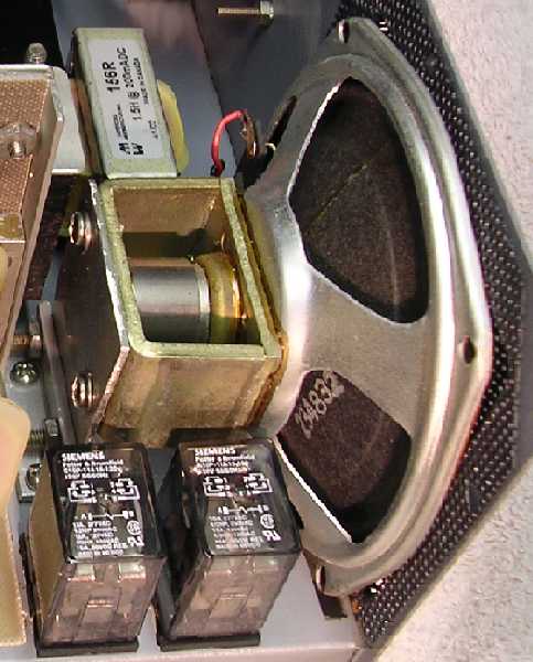
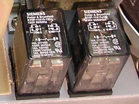
1. A power-on relay, where the primary current to the power transformer is controlled
by a set of high current contacts instead of the 32S3 or KWM2 power switch.
The 32S3 or KWM2 power switch will only carry the current required by the relay
coil which is a small fraction of an amp. This will lessen the load on the power
switch contacts and extend their life.
2. Full metering of the high-voltage, low-voltage, and bias supplies. It's not
really necessary but it's nice to watch how the supplies respond with loads.
And, meters really impress visitors to the shack.
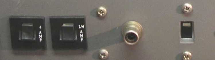
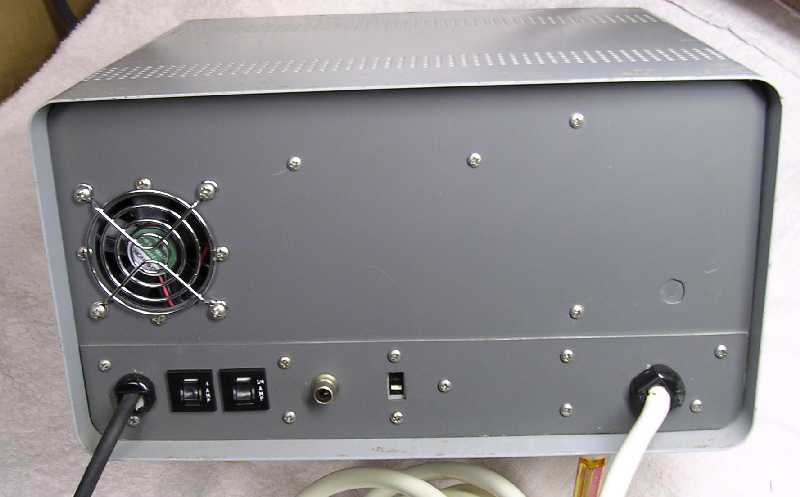
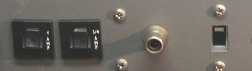
3. Resettable circuit breakers instead of fuses. I don't know if these thermal
breakers will respond fast enough to protect anything except, possibly, in a
short circuit condition. But I decided to give them a try and see how they worked
out.
4. A test switch that operates the supply. It would be used instead of a wire
jumper to turn it on and off. It just makes for easier operating during testing
and troubleshooting.
5. A speaker to eliminate another box in the shack. A Motorola mobile speaker
is used instead of a general purpose type.

TUBES OR SILICON
The first concern I debated was whether to use tube or silicon
rectifiers. I like the soft turn-on characteristic of tube rectifiers where
the high voltage doesn't appear until after the filaments have had a chance
to start heating up. This has to be easier on tubes than hitting them with high
voltage and then start heating their filaments. Another consideration was the
transformer itself. Transformers in the HT-32/37 rigs seem to have a higher
than normal failure rate associated with a 5 volt rectifier filament winding
shorting to another winding. Apparently the 5 volt windings were provided an
inadequate margin of safety with regards to insulation. Thus I had a little
hesitancy with using these 5 volt windings at high potential. I would also have
to contend with the heat from the tubes in the enclosed cabinet. Ultimately,
it came down to available space. When I began to physically layout the parts,
it became obvious a couple of big rectifier tubes would take up too much chassis
space. Thus I decided to go the silicon route.
After the silicon decision I decided to include a soft-start circuit to minimize
turn-on stresses to the diodes. This soft-start circuit is where the initial
line current is substantially limited until the filter capacitors have charged
up. I found a delay of only about 1/4 to 1/2 second was more than adequate to
provide this effect. After the delay full line voltage is applied to the power
transformer. Another thought I had was to put another delay timer in the supply
that would initiate the soft-start about 20 seconds after filament voltage was
applied to the transmitters. I decided to drop this feature as 'excessive'.
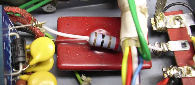
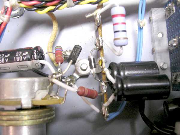
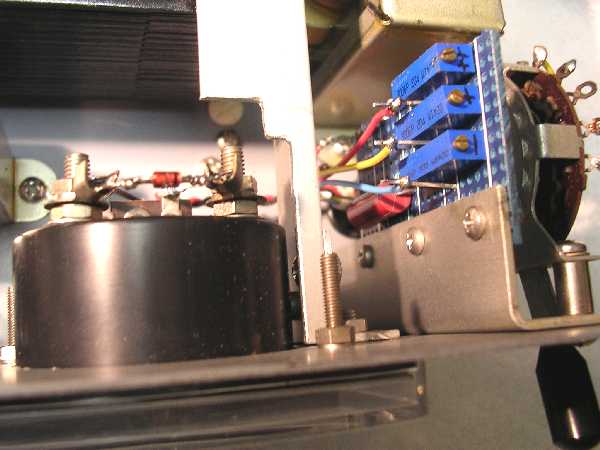
Also after the silicon decision I included transient protection as much as possible
for the diodes. This included a transient/surge absorber or varistor across
the transformer primary, an RC snubber across the high voltage secondary, and
RC equalizing networks across all the high- and low-voltage diodes. 3-amp diodes
with a robust 200 amp surge rating were also used.


THE HIGH VOLTAGE SUPPLY
I originally intended to follow the Collins design and use a
resonant filter choke filter in the high voltage circuit to limit the no-load
voltage. I previously didn't have much success with this type of circuit, probably
a result of the choke not being close to its expected value. But I decided to
give it another try here.
The 516F-2 uses an 8 henry, 150 mA, 200 ohm choke in the high voltage circuit.
It also uses a 0.05 mfd capacitor to resonate this choke to 120 Hz. If you calculate
the inductance needed to resonate a 0.05 mfd capacitor at 120 Hz you come up
with 35 henries. This is quite removed from the listed 8 henry choke. Could
this be a swinging choke where the inductance is much higher at low currents?
I had never seen mention of it being 'swinging' in any literature before. An
8 henry choke would need about 0.22 mfd to resonate it at 120 Hz.
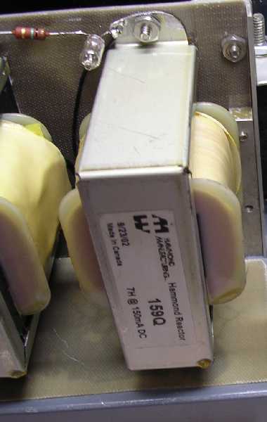
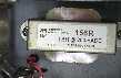
Looking for chokes these days shows the availability is quite limited. Hammond
Manufacturing seems to offer some reasonably priced units. Their closest to
the Collins 8 henry unit is a 7 henry, 150 mA, 100 ohm unit, their model 159Q.
The only problem is that its maximum operating voltage is only rated at 500
volts DC. To get a higher voltage unit I would have to get one of their enclosed
units which has twice the volume and price. I decided to try the 159Q choke
and look closer at its voltage limitation later.
Since I wanted to resonate this choke at 120 Hz while drawing bleeder resistor
current, I needed to know its inductance at about 20 mA. Communicating with
Hammond I found they couldn't provide this data, just its inductance at rated
current. Now, measuring inductance with various DC currents is not something
your common bridge or meter will do. Searching the internet I came across an
interesting article that appeared in EDN Design Ideas on July 6, 1995 by H.
B. Farensbach. The article showed how one could measure inductance with DC superimposed
without it being too complicated. I played around with that circuit and was
able to develop some inductance vs. current curves for the Hammond 159Q choke.
(That EDN article may no longer be accessable at EDN archives;
click here for the Farensbach article in .pdf file. Farensback
talks about making a special transformer; I just used a 5 VAC, 3A filament transformer
and a test frequency of 120 Hz which worked just fine. I used an oscillator
driving a PA amplifier with a 70 volt output to drive the filament transformer,
however, I'm not sure I really needed the amplifier but didn't pursue that further.)
While developing the inductance curves for the 159Q choke I also decided to
see how varying its air gap changed its inductance. The choke comes with a nominal
0.02 inch gap and I took additional measurements with gaps of 0.01, 0.003, and
zero inches. I measured the stock choke inductance at about 6 henries rather
than its rated 7 henries. However, it did stay fairly constant up to about 250
mA. Naturally, decreasing the air gap showed increasing values of inductance
at low currents and subsequently less inductance at the higher currents. With
a decreasing air gap the core is saturating with less current. An air gap decreases
the inductance while increasing the operating current before the core saturates.
One interesting effect was with the zero air gap. Here the 159Q choke has an
inductance about 15 henries up to about 25 mA decreasing to 2.5 henries at 150
mA and just under 2 henries at 200 mA. This high inductance, while not as high
as the critical inductance with only bleeder resistor current, should limit
the unloaded voltage quite well. As the load current increases and lowers the
inductance, it would operate even more below the critical inductance and start
approaching a capacitor input filter. I decided to test the choke in this mode
as a 'swinging' choke before trying to resonate it.
The high voltage was tested using an unmodified choke as well as the swinging
choke. The results were:
| |
7
Henry Choke
|
15-2.5
Swinging Choke
|
Stock
516F-2
|
| |
------------
|
--------------------
|
------------
|
|
NO
LOAD:
|
1004
VDC
|
917
VDC
|
1060
VDC
|
|
LOADED:
|
730
VDC
|
734
VDC
|
752
VDC
|
|
VOLTAGE
DROP:
|
274
VDC
|
183
VDC
|
308
VDC
|
Out of curiosity I shorted the swinging choke under load
to see what a pure capacitor-input filter would provide. The voltage went up
from 734 to 1007 volts. A swinging choke with even less minimum inductance would
keep the loaded voltage even higher here. However, with these gratifying results
I decided to forget any attempts at a resonant choke filter and use it as a
'swinging' choke-input filter.
That 500 volt maximum rating on the choke now gave me a little concern. In a
transformer, exceeding the voltage rating can result in a winding-to-winding
breakdown or a winding-to-core breakdown. Since a choke is a single winding
at essentially the same potential, the maximum voltage rating would only involve
a winding-to-core breakdown. Normally the core is grounded for safety's sake.
But if the core is left ungrounded, any breakdown must occur between the winding-to-core
AND the core-to-ground. The breakdown voltage is increased because of the core-to-ground
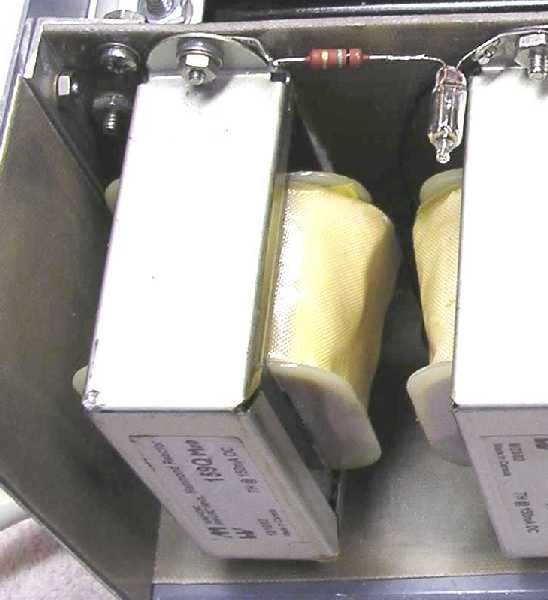
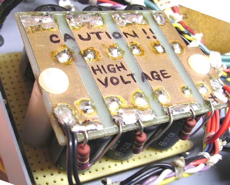
isolation. Since the choke was going to be installed within an enclosed cabinet,
I elected to isolate its core from ground with fiberglass board and appropriate
warning labels. I did include a circuit with a neon bulb that would have a warning
glow should the choke develop any winding-to-core leakage or short.
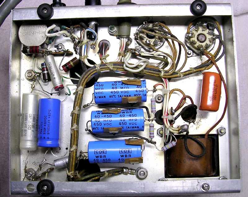
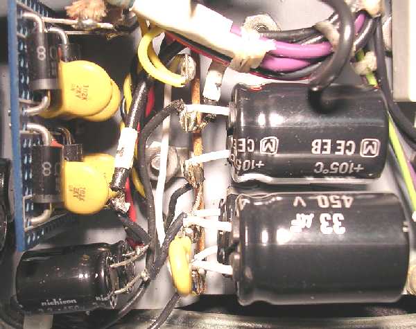
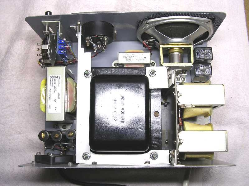
I also increased the filter capacitance from that used in the 516F-2 to compensate
for the decreased choke inductance at the higher currents. I used capacitors
that give a total high-voltage capacitance of 33 mfd whereas the 516F-2 uses
10 mfd.


LOW VOLTAGE SUPPLY
For the low voltage supply the 516F-2 transformer has a much
higher output voltage than the transformer I was using: 425 volts vs 270 volts.
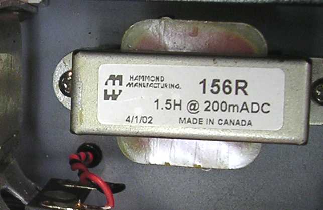
I followed the 516F-2 filtering fairly close, using a 7 henry input choke and
a 1.5 henry output choke whereas the 516F-2 uses a 8 henry input choke and a
1 henry output choke. With the lower transformer voltage to the filter, it was
obvious the DC output voltage was going to be too low. I had to use a capacitor
input filter to compensate for it. I settled on 8 mfd for the input capacitor
that produced almost identical results with the 516F-2 between unloaded and
loaded conditions as follows:
| |
LOW
VOLTAGE, NO CAP
|
LOW
VOLTAGE, 8 MFD
|
STOCK
516F-2
|
| |
-----------------
|
-----------------
|
------------
|
|
NO
LOAD:
|
292
VDC
|
383
VDC
|
385
VDC
|
|
LOADED:
|
225
VDC
|
278
VDC
|
273
VDC
|
I also increased the output capacitance to improve the filtering.


BIAS SUPPLY
The only problem I have ever had with a 516F-2 bias supply, other
than the selenium rectifier originally supplied, was its variance with line
voltage. This directly caused the idling plate current to vary with changing
line voltage. Granted this is not a real big problem! I generally used the 516F-2
bias circuit except for the addition of a regulating zener diode and an additional
filter capacitor. It's output now remains constant with varying line voltages
because of the zener and the additional capacitor has reduced ripple voltage
on the bias down to very low levels.


MISCELLANEOUS TOPICS
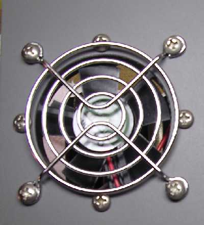
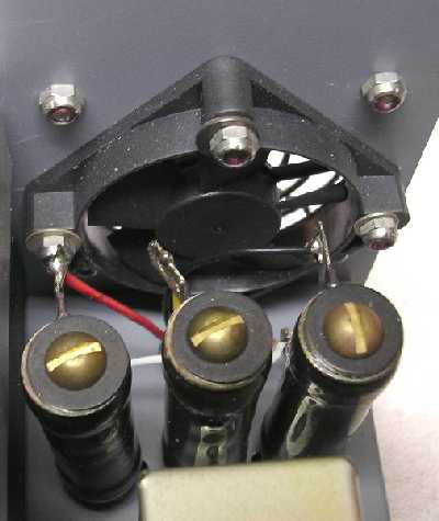
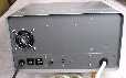
Another item added to the supply is a small 12-volt fan about
2-inches in diameter that exhausts heat out of the cabinet from around the 25
watt bleeder resistors. This fan and the power-on lamp are powered from the
rectified 5-volt windings. No filtering is used after the rectifiers so they
only provide about 8-9 volts equivalent DC. This voltage lets the fan run at
less than full speed with a lower noise level and increases the lamps's life
by using slightly less than rated voltage.


I also elected to use a separate filament transformer rather
than use the power transformer's filament winding. This was to eliminate a load
on the power transformer that would let it run cooler, hopefully lengthening
its life and maybe improving its regulation a little.

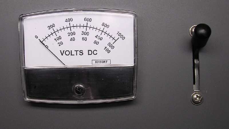
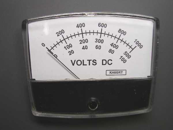
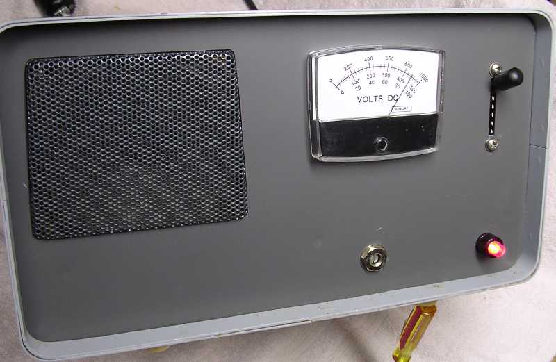
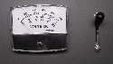
The meter originally started life as a nice-looking Radio Shack
Vu meter I had around. These Vu meters are nothing more than a sensitive DC
microammeter with a diode bridge and a couple calibrating resistors tossed in.
After measuring the movement's internal resistance and the current needed to
produce full scale deflection, the dropping resistors needed for the different
voltage scales were easily calculated. I used a 1000 volt scale for the high-voltage,
a 500 volt scale for the low-voltage, and a 100 volt scale for the bias supply.
A little artwork on the Visio program and I quickly had a new scale glued onto
the backside of its faceplate. Multiturn trimmers were included to calibrate
the meter right-on.


Teflon insulated wire was used throughout because I like working
with it and its insulating capability is outstanding. It's nice to solder it
and not have the insulation melt back.
All the electrolytic capacitors used have a 105 degree centigrade rating rather
than the common 85 degree rating. I think a few cents more for the higher temperature
ones will pay off with less problems in the future.
SUMMARY
In summary, the following table shows how well my completed supply
compares to the 516F-2:
| |
MY
POWER SUPPLY
|
516F-2
|
| |
-----------------------------
|
--------------------------------
|
| |
VOLTS
DC
|
VOLTS
RIPPLE P-P
|
VOLTS
DC
|
VOLTS
RIPPLE P-P
|
| |
---------
|
------------
|
---------
|
------------------
|
|
B++,
NO LOAD:
|
884
|
2
|
1089
|
6
|
|
B++,
LOADED:
|
755
|
20
|
779
|
20
|
|
|
DROP
= 129 VOLTS
|
DROP
= 310 VOLTS
|
|
|
|
|
|
|
|
B+,
NO LOAD:
|
373
|
0.02
|
388
|
0.2
|
|
B+,
LOADED:
|
283
|
0.05
|
286
|
0.4
|
|
|
DROP
= 90 VOLTS
|
DROP
= 102 VOLTS
|
|
|
|
|
|
|
|
BIAS:
|
46-88
|
0.02
|
55-74
|
0.4
|
These readings were taken with a constant 117 volt AC line voltage
with both the high- and low-voltage supplies loaded.
So, did I succeed in keeping my cost down by building it? No. The cost for new
parts actually included in the power supply ran about $225. This doesn't include
anything from my well-stocked junk box which included the power transformer, meter,
cabinet, hardware, terminal strips, speaker, wire and whatever else I picked up
in years past. Granted some was for features I 'added in'. But from a long time
builder, I'd still do it again!
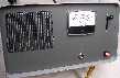


Eventually I'll be putting some labels on the panels.


END