
Here is a third kit. It is an oscillator circuit I have tried and it works. It is based on the oscillator circuit found in the QST magazine from January 1997 on page 32. I used a cmos oscillator running at 55.580MHZ instead of the 32MHZ oscillator like is used in the article. The oscillator uses a 74AC86 exclusive or gate as a frequency multiplier. The circuit has an output frequency of 222.320MHZ due to the x4 multiplier circuit. The circuit is made up of four resistors, two capacitors and the 74AC86. The circuit and the oscillator operate from a five volt supply. The output of the final exclusive or gate can be fed into the one of the two inputs of each gate on the 74LS06 Hex Inverter gate. The outputs of all six not gates are tied together and connected to the five volt supply through a .15uH inductor. These outputs are also fed through a .1uF capacitor into a five element Chebyshev filter and then to the antenna. The output of the 74AC86 can also be filtered and fed into a NE602A mixer / oscillator as the local oscillator for a receiver.
The kit pictured above is used for converting a single band ham receiver to any other ham band. The kit costs twelve dollars. The circuit above is the six meter to two meter converter so that a standard two meter receiver can be used to listen to six meters. The NE602A will work up to 500MHZ. You can cascade two of the NE602A chips and build one of the 150MHZ oscillator circuits on this page and feed it to both of the NE602A that will allow you to listen to the 70CM band on a two meter receiver.
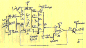
Here is another kit. It is for delta-modulation and uses a 74LS191 Up / Down counter, a LM741 operational amplifier and a LM555 timer / oscillator. The LM555 is set up as a 50KHZ oscillator that drives the clock input of the 74LS191. The four outputs of the counter are fed into a resistor network to give sixteen levels of voltage from zero volts to five volts. The output of the network is fed into a 1uF electrolytic capacitor and then to a two kilo-ohm potentiometer that is tied to ground on the opposite end. The addition of the 1uF capacitor into the circuit removes the DC bias from the output signal. The wiper of the potentiometer is tied into the positive input of the LM741. The potentiometer gives the builder a point to adjust the output of the counter circuit to match the audio signal. The negative input of the operational amplifier is tied to a 5 volt peak to peak maximum audio signal. The output of the LM741 is tied to the down / up input of the counter and also to the transmitter control circuitry. The output of the LM741 can be passed through a one kilo-ohm resistor to the base of a 2N2907 PNP transistor, then tie the collector to a positive voltage supply and last tie the emitter to the power input of your transmitter. The PNP transistor provides a level translation from zero volts to the transmitter positive supply voltage. This kit is available from the club for ten dollars.
The kits do not include the circuit boards. We do not have circuit boards available for the kits at this time so I suggest using a Radio Shack 276-170 circuit board. If you like, buy the matching breadboard and you can assemble the kit and test it before you solder it.
Here is another circuit for you to try. Use a 74S124 which is a Dual Voltage Controlled Oscillator that is capable of up 85MHZ and is available from the Texas Instruments webpage. Set one side of the oscillator chip to range between 35MHZ and 37.5MHZ. Next connect the output of the oscillator to the input of the 74AC86 circuit mentioned above to get a 140MHZ to 150MHZ oscillator output. Then connect the output of the circuit mentioned above to a three times multiplier circuit to get an oscillator output range of 420MHZ to 450MHZ. The other oscillator can be set to range from 55.5MHZ to 56.25MHZ and then applied to the 74AC86 circuit to give an oscillator range from 222MHZ to 225MHZ. Another idea is to set the VCO to range from 45.1MHZ to 46.4MHZ, apply that to the 74AC86 circuit giving 180.4MHZ to 185.6MHZ out and then filter the fifth harmonic from that giving a range of 902MHZ to 928MHZ. When you set the vco input voltage for the frequency you need, you can mix a low level audio signal with the input voltage to get narrow band FM from the oscillator.
To request other schematics or board layouts please click here
KG9KV.For the mailing address of the club and hard copy fees for the circuit board layout and / or schematic
click here.Click on the treasure hunter to dig up some more schematics.

QRP Club List: http://home.sol.no/~janalme/rules/qrpfield.txt http://www.qsl.net/kc8kfi http://www.scott.net/~eighmy/ham.html http://www.waterw.com/~n2apb/ham/ham.html http://www.howes-comms.demon.co.uk/ http://www.qsl.net/al7fs/index.html http://members.xoom.com/sm0vpo/ http://www.nett.is/%7Etf5bw/ira/links/qrp.html http://www.njqrp.org/data/links.html http://home.cdsnet.net/~kb7fci/ http://www.qsl.net/tcarc/ http://www.qsl.net/ad5xa/ http://www.homepages.together.net/~ruggiero/ http://www.rac.ca/ University of Arkansas Amateur Radio Callsign Database http://www.wndu.com/ http://www.22wsbt.com http://www.nsknet.or.ip/~ja9mat/index.html http://www.geocities.com/ResearchTriangle/8254/index2.html/ Antenna Links
1.8 MHz = 4.7nf 3.5 MHz = 2.2nf 7.0 MHz = 1.2nf 10 MHz = 820pf 14 MHz = 560pf 18 MHz = 470pf 24 MHz = 390pf 28 MHz = 330pf 50 MHz = 180pf
![]() -
-
![]()