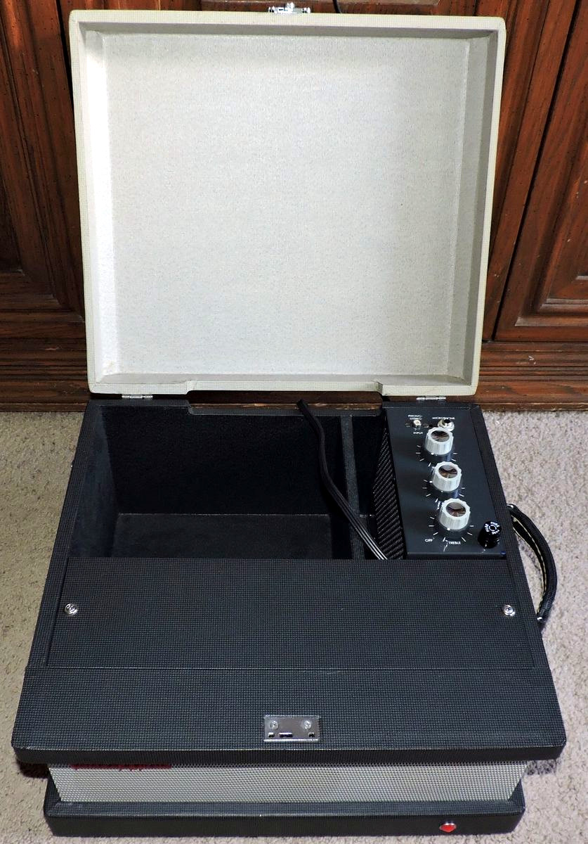
Many years ago, I was given a late 1950s vintage Voice-of-Music Model 714 reel-to-reel tape recorder by a family relative. The tape recorder came with a Model 166-A Extension Speaker that included a Model 8809-8810 amplifier for the purpose of playing stereo tape recordings.
At the time of its design, there were a number of competing stereo tape recording standards under development, and the tape recorder, itself, could not record in stereo. As such, the external amplifier saw very little use.
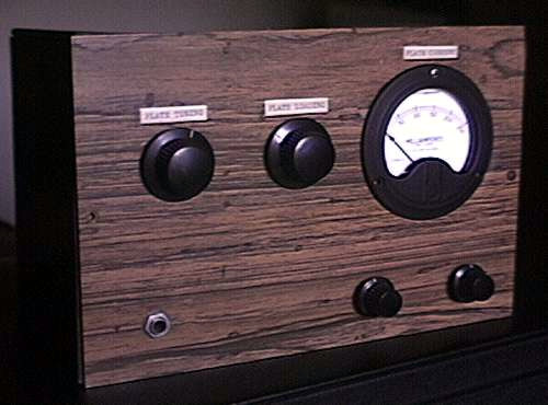
When I became an Amateur Radio Operator, I looked through my electronics inventory to see what components I might have available to build a small transmitter. I decided to build a crystal-controlled tube-based CW transmitter because such a design would achieve the greatest output power while requiring the fewest number of components. The Voice-of-Music amplifier became one of the sources of components for my transmitter.
About three decades later, I came across many of the parts taken from my old Voice-of-Music amplifier, including the original tubes, tube sockets, potentiometers, transformers, and knobs. Since these parts only took up space and served no useful purpose by themselves, I thought it might be a worthwhile effort to put them together again and reconstruct the amplifier as it was originally designed. The only thing missing was the original metal chassis. As such, I decided to re-design the physical layout of the amplifier on a new chassis completely separate from the original speaker enclosure.
Several variations of this design are known to exist. In some versions, the 500 ohm, 5 watt resistor in series with the cathode of the 6X4 rectifier is 1000 ohms. I decided to play it safe and use the larger of the two values in my construction. Some models used a potentiometer as a hum-balance control instead of a center-tapped filament transformer. Others added some DC blocking components to the inputs of the amplifier.
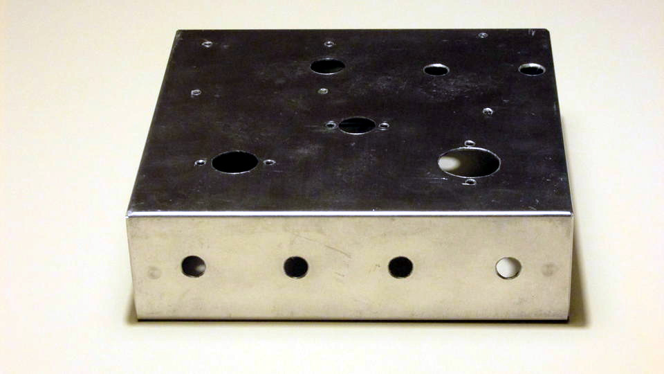
I gathered together all the components that would be mounted on the top and side surfaces of the chassis, developed an appropriate layout of the components, and purchased a 7"x7" Bud Industries Model AC-405 aluminum chassis to re-construct the amplifier.
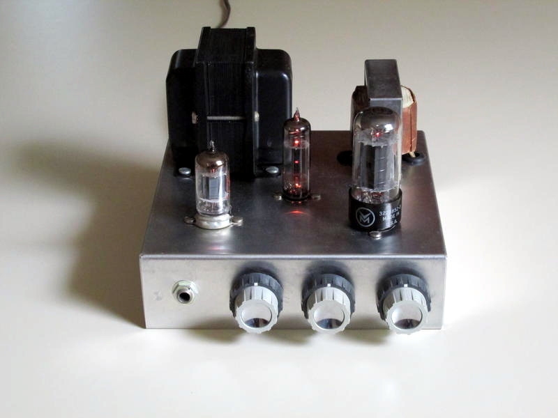
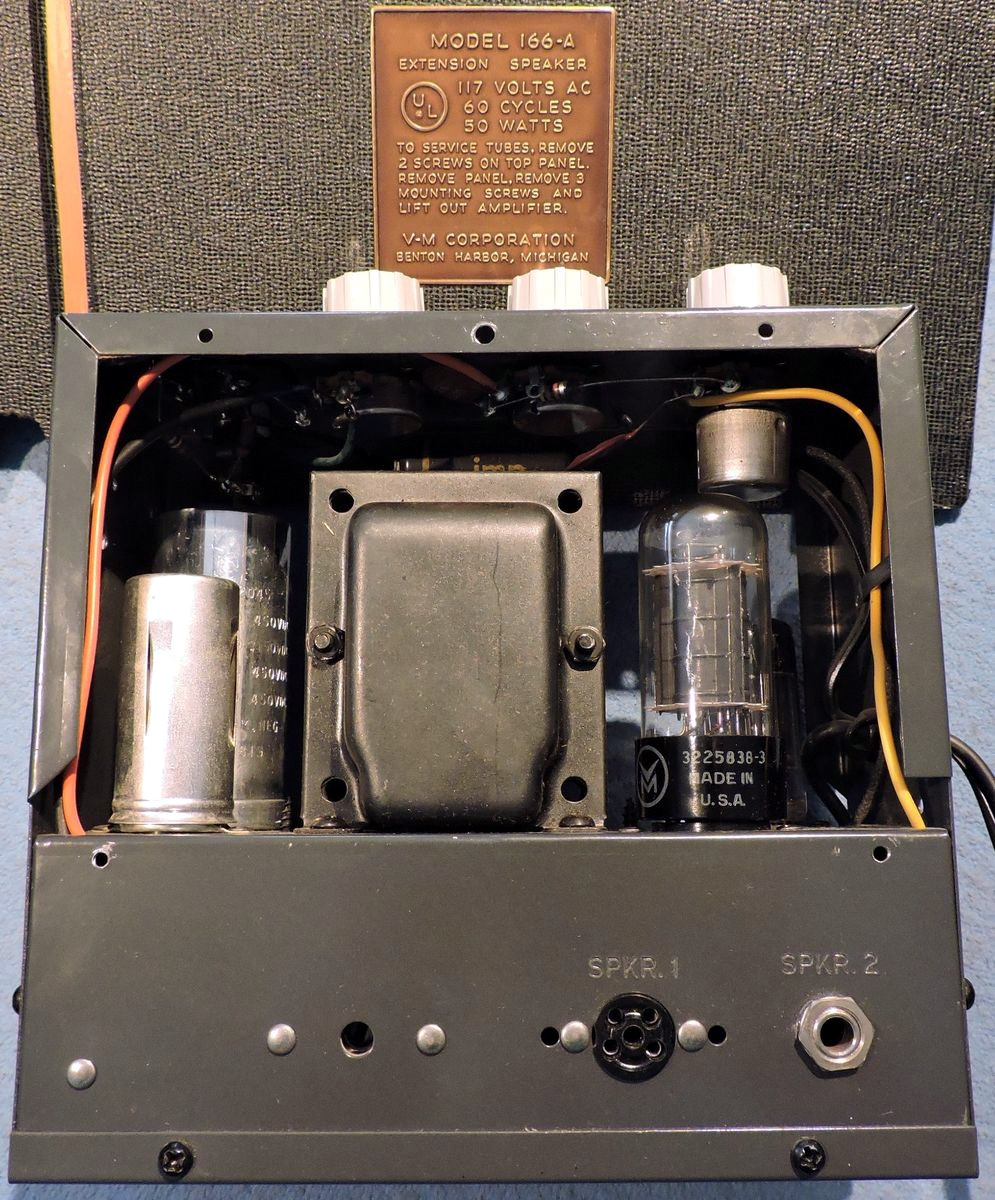
The tube visible on the left side of the chassis is the 12AX7 dual triode. The 6X4 dual rectifier is located in the center, and the 6V6GTA beam power amplifier tube is visible on the right. The layout I chose is less condensed than that of the original design, and the shield that originally surrounded the 12AX7 is no longer required.
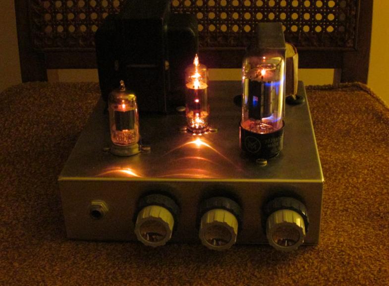
This amplifier pushes the 6V6GTA rather hard, and some color can be seen where the electron beam is focused on the plate of the tube. The blue glow on the inside surface of the tube envelope is the result of the glass being bombarded by high velocity electrons that have leaked through small gaps in the tube's plate. This effect is evidence of a good tube with a hard vacuum, which is good news for a 60+ year old tube.
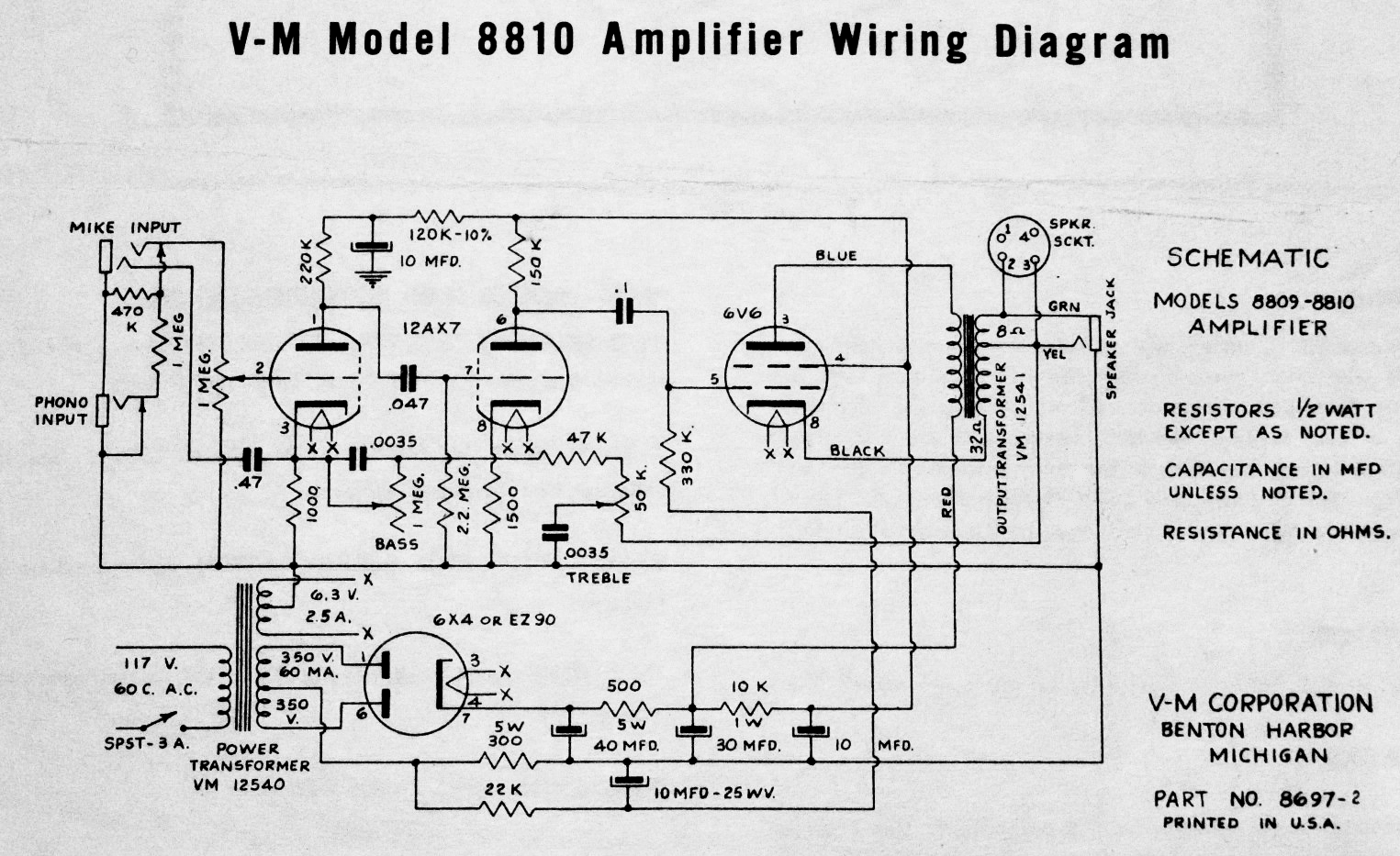
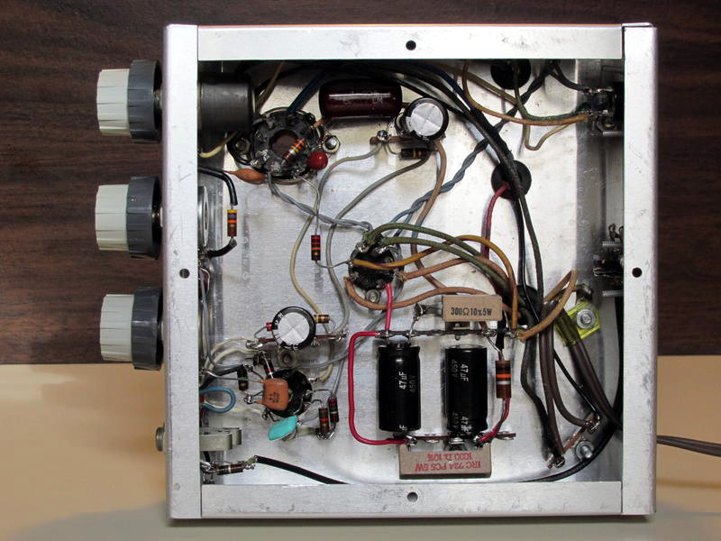
The amplifier is a fairly simple three-stage design that employs several feedback networks to minimize distortion and control bass and treble levels. It was designed to closely match the tonal qualities of the companion tape recorder.
The manufacturer claimed a rated output power of 5 watts with less than 2 percent distortion, a frequency response of 30 Hz to 20 kHz (+/- 2 dB at 5 watts), a phono input sensitivity of 0.3 volts, and a microphone input sensitivity of 0.02 volts for full output. A treble boost of 15 dB at 10 kHz and the bass boost of 12 dB at 50 Hz are also claimed. And like the companion tape recorder, the power switch is co-located on the Treble control.
The following voltage measurements were taken to ground from the re-built amplifier under the conditions of a 119 volt RMS (60 Hz) line voltage, with no audio signal applied, using a DMM having a 10 megohm impedance:
| Pin 1 | Plate #2 | +98.5 volts |
| Pin 2 | Control Grid #2 | -0.25 volts |
| Pin 3 | Cathode #2 | +0.57 volts |
| Pin 4 | Filament | Filament (Tied to Pin 5) |
| Pin 5 | Filament | Filament (Tied to Pin 4) |
| Pin 6 | Plate #1 | +166.5 volts |
| Pin 7 | Control Grid #1 | 0 volts |
| Pin 8 | Cathode #1 | +1.31 volts |
| Pin 9 | Filament Center Tap | Filament |
| Pin 1 | Plate #2 | 369 volts AC |
| Pin 2 | No Connection | No Connection (Tie Point) |
| Pin 3 | Filament | Filament |
| Pin 4 | Filament | Filament |
| Pin 5 | No Connection | No Connection |
| Pin 6 | Plate #1 | 369 volts AC |
| Pin 7 | Cathode | +383 volts DC |
| Pin 1 | No Connection | No Connection |
| Pin 2 | Filament | Filament |
| Pin 3 | Plate | +319 volts DC |
| Pin 4 | Screen Grid | +298 volts DC |
| Pin 5 | Control Grid | -15.5 volts DC |
| Pin 6 | Empty Pin | Tie Point (No Connection) |
| Pin 7 | Filament | Filament |
| Pin 8 | Cathode & Beam Forming Plates | +0.644 volts DC |
Note that what is defined as the second triode of the 12AX7 forms the first stage of amplification, and vice-versa. The second triode in a 12AX7 typically has slightly higher transconductance than the first, and is a better choice for the first stage of amplification. The small negative voltage appearing on the control grid of the first triode stage is the result of what is commonly referred to as "contact potential" bias.
When a microphone is inserted into the amplifier, an extra set of contacts on the microphone jack bypasses to ground the negative feedback network driving the cathode of the first triode stage, raising the gain of the stage, and disabling the function of the bass and treble controls.
The audio output transformer has a teriary winding connected in series with the cathode of the 6V6GTA. This connection provides negative feedback around the 6V6 to help reduce its distortion levels, lower the amplifier's output impedance, and keep it constant under the dynamic load presented by the speaker.
The 6V6GTA operates with a zero-signal plate dissipation of approximately 14 watts, which is the maximum rating for the tube in free space. A fixed control grid bias of -15.5 volts is developed across the 300 ohm, 5 watt resistor in the power supply, a resistor through which all circuit current is drawn. The 6V6 is a scaled down version of the 6L6 beam power amplifier tube, and carries ratings similar to those of the 6CM6, 6AQ5, and 7C5.
In conclusion, after being made "whole" again through the reconstruction described here, the amplifier works and sounds just as it did in its original form.
73 de John, KD2BD
August 2019

|
John Magliacane Amateur Radio Operator: KD2BD |