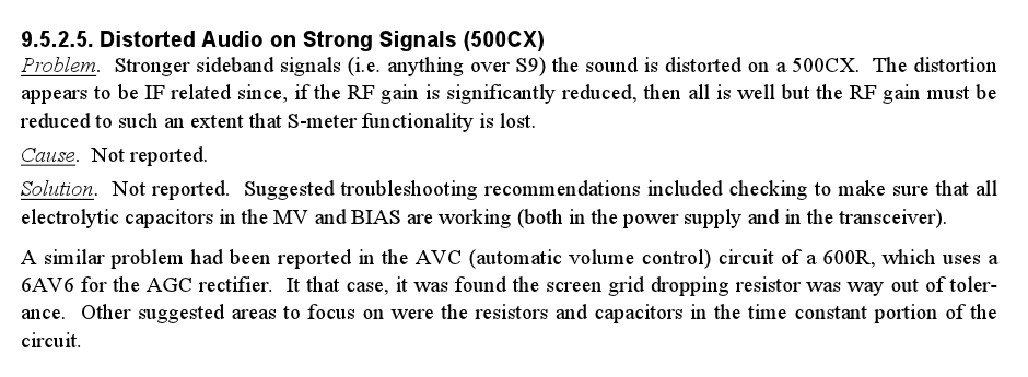
The Swan 500CX employs audio-derived AGC (and ALC) circuitry that I
have found can benefit from some minor tweaking. In particular, my
transceiver (Serial# I 611252) has always suffered from some level
of audio distortion when receiving very strong signals. The "Swan
Compendium" addresses this issue, but does not offer any definitive
cause or solution:
The distortion in my case was found to be the result of the first
receive audio amplifier stage (V10B, 12AX7) being over driven by the
product detector. V10B typically produces about 30 volts pp of audio,
but can be driven to three times this level on very strong signals.
Such high levels cause severe clipping of the audio waveform, and limits
the AGC voltage from rising to the levels needed to prevent the overload
from occurring in the first place.
Insufficient AGC action is especially problematic at low audio frequencies.
The solution was to simply increase the size of the audio coupling
capacitors in the AGC circuitry to improve its low frequency response.
A further improvement can be made by decreasing the size of the AGC
filtering capacitors to improve the AGC's transient response time.
Discussion
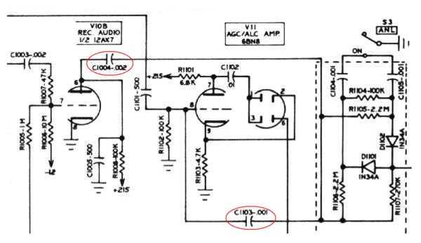
Audio from plate of the 12AX7 (V10B) is capacitively coupled to the grid
of the AGC amplifier (6BN8, V11), through a series combination of C1004
(0.002uF) and C110 (0.001uF). This arrangement produces a total series
capacitance of just 666.66 pF and forms a highpass filter in conjunction
with V10B's plate resistance, V10B's 100k ohm load resistor (R1008),
and V11's 100k ohm grid resistor (R1102).
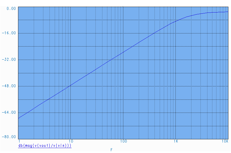
At 300 Hz, the response of this network is down 14 dB relative to its
response at 3000 Hz:
Obviously, the AGC's frequency response is neither as wide nor as flat
as the passband of the 2.7 kHz wide crystal filter. In fact, the amount
of AGC voltage at 300 Hz is only 20% of that available at 3000 Hz.
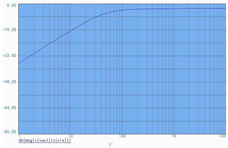
Increasing the capacitance of both C1004 and C1103 to 0.047 uF lowers
the cutoff frequency to 48 Hz, keeping the AGC response flat across the
entire 300 Hz to 3000 Hz audio bandwidth:
C1004 should be rated to 300 volts or greater, and is located between
Pin 6 of V10B and the adjacent circuit board containing the ANL and
carrier oscillator circuitry. C1103 sees significantly less DC voltage,
and is located between Pin 8 of V11, and the ANL and carrier oscillator
circuit board.
Improving AGC Transient Response
With these changes in place, brief bursts of distortion can still occur
during the onset of a very strong signal. This distortion occurs during
the fraction of a second it takes the AGC's filter capacitors to fully
charge. Reducing the size of these capacitors reduces the associated
RC time constant, improves the AGC's transient response, and reduces the
"AGC attack" distortion.
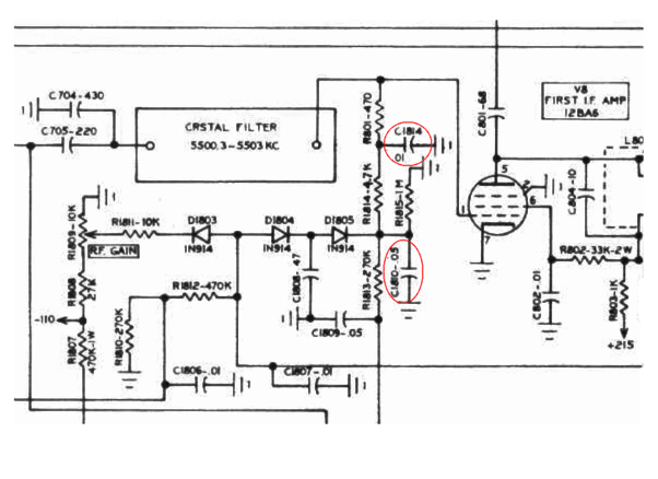
I found that decreasing the capacitance of C1810 from 0.05 uF to 0.0047
uF, and C1814 from 0.01 uF to 0.001 uF noticeably improved AGC attack
time without introducing any oscillations within the AGC loop.
The component changes described here not only affect the receiver's
AGC, but also the operation of the transmitter's ALC. There have been
no observed problems with transmitter operation after these component
changes were made.
A weak 12AX7 in V10's position can also cause strong signal audio
distortion. I typically keep the stronger of the two 12AX7s in V10's
position, and the weaker one in the microphone amplifier stage (V14),
since any lack of gain in this stage can be offset by simply raising
the MIC GAIN control.