There are about 5,000 different antenna designs in existence. Of
those many designs, horizontal omnis seem to be the one design
most shrouded in mystery in the amateur radio world. UHF
applications requiring horizontally polarized omni-directional
antennas usually use an Alford Slot, its cousin the Rib-Cage
Slot, or a loop antenna. Unfortunately, technical references
containing slot antenna information rarely contain practical
design information required to build such antennas reliably, and
few experimenters have access to the resources needed to fully
analyze the radiation properties of their antennas over wide
bandwidths. A low VSWR is often mistaken as meaning an antenna is
functioning well. However, VSWR means nothing when it comes to
radiation patterns and antenna gain.
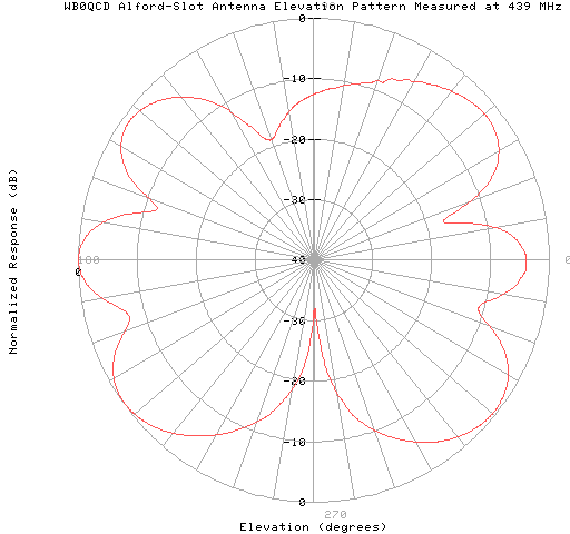
One type of UHF slot antenna that has gained popularity over the past several years is the a 2-wavelength Alford Slot. This type of antenna has been built using either a solid pipe or a "rib-cage" design with similar results. Unfortunately, this design has been shown to perform poorly when tested on a commercial antenna range. Some more ambitious designs stack a pair of 2-wavelength slots vertically on a common mast in an attempt to achieve 3dB greater gain, but the vertical pattern is further worsened by this, and the extra gain is never realized in directions favoring the horizon where it would reach the farthest terrestrial distance.

While both resonant and non-resonant slots are popular with UHF television broadcasters, their design differs drastically from the 2-wavelength Alford Slot used by amateurs. No commercial UHF broadcaster uses a 2-wavelength slot antenna, and for good reason. Resonant UHF slot antennas used by broadcasters are typically half-wavelength resonant (physically about 0.7 wavelengths in length) and are stacked vertically with approximately one wavelength spacing to increase vertical directivity and system gain. These antennas perform well, but only over a very narrow bandwidth (seldom over 2 or more NTSC television channels) limiting their use in 70-cm in-band ATV repeater applications. See Doug Lung's January 1996 and February 1996 RF Columns for an overview of how commercial UHF-TV slot antennas work.
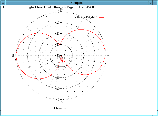
A single element full-wavelength rib-cage slot antenna 34.75 inches in length has been tested and found to perform better than a 2-wavelength slot. Although designed for the 70-cm amateur band, this slot length was found to perform much better at 400 MHz. The slot is fed close to its center with 50-ohm line through a 4:1 half-wavelength coaxial balun.

The first plot shows the normalized radiation pattern of the Rib Cage Slot antenna measured at 400 MHz. The patterns were found to deteriorate at higher frequencies.

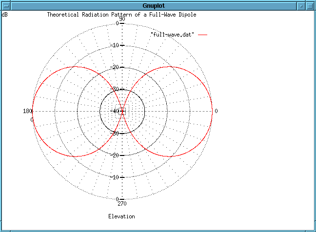
The second plot shows the theoretical radiation pattern of a full-wavelength radiator. The 3dB beamwidth is 47.8 degrees.

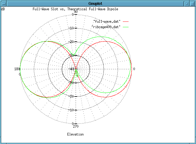
The final plot shows both radiation patterns plotted together so that their similarities can be closely examined. Note that both patterns appear to be nearly identical on the left-hand side of the graph. The radiation tilt on the right-hand side is a bit of a mystery, and may be due to a fault of the balun used to feed the balanced slot with an unbalanced coaxial transmission line.
Several antenna manufacturers targeting the amateur radio market have recently developed loop antennas of various shapes and sizes for horizontally polarized, omni-directional applications. Unfortunately, horizontal loops are not truly omni-directional unless they are made small in terms of wavelength (which then restricts their operating bandwidth) and end loaded with capacitance to bring them back into resonance.
Unlike slots, horizonal loops and dipoles of various shapes ("V" and turnstile) offer nothing in terms of vertical directivity. They radiate equally well in all vertical directions. Such elements, if stacked vertically for greater gain, must be stacked exactly one half-wavelength apart to cancel radiation that would otherwise occur along the axis of the antenna and never contribute to the field radiated toward the horizon. Of course, this critical spacing is frequency dependent, diminishing the performance of such an antenna over a wide bandwidth of frequencies.
Several years ago, a horizontally polarized, omni-directional antenna consisting of an array of vertically stacked "V" dipoles was purchased and tested prior to installation. The antenna was not targeted for ATV use, but rather for commercial radio applications. Range testing showed that even this antenna offered poor performance, and was returned to the manufacturer for a full refund.
An excellent horizonally polarized, omni-directional antenna appears to be one that uses stacked broadband elements that radiate as slots so that little or no radiation occurs along the axis of the antenna. Such an antenna has been used for many years in VHF television broadcasting and is finding applications in with the world of high definition television It is called the Batwing, or Master's Superturnstile.
Efforts are underway to design and build such an antenna for ATV repeater service. Progress has been slowed somewhat due to many unanswered questions relating to mechanical and materials issues. Nevertheless, plans have been drawn up, and as soon as the right combination of people, materials, and labor can be assembled, a prototype will be built, tested, and installed.
Results of our findings will be posted here.
 Return to the
Brookdale ATV Repeater Home Page