
15 METER VXO-TUNED
CW TRANSMITTER
Cost estimate: $40 (excluding crystals)
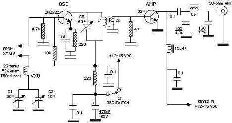
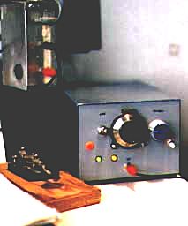
An easy-to-build and affordable CW rig that puts out about 500 milliwatts on 15 meters, this simple modification of W7ZOI's classic two-stage "Universal QRP Transmitter" (also known as the "Little Joe" ) features a VXO circuit that "warps" each crystal frequency by as much as 10kHz or more for increased flexibility. This transmitter's oscillator runs throughout the transmit period; voltage is keyed to the amplifier section while the oscillator is on. After construction, tuneup is a snap: connect a 12-15 VDC power source and 50-ohm dummy load or RF wattmeter -- or even small incandescent lamp across the antenna terminals: I use a 7.5V 0.22 bulb which is a 1.65W lamp [Watts = Volts X Amps] -- and tune a monitoring receiver to the anticipated transmit frequency. Flip on the oscillator switch and adjust C3 until a tone is heard on the receiver. Play with C1 and notice the shifting of frequency (the crystal frequency DECREASES as C1's capacitance INCREASES). Depress the key and adjust C3 for maximum output [maximum brightness if using an incandescent lamp]. Tuneup adjustment is now complete. Hook up an appropriate antenna (a 40-meter dipole works great on 15 meters without use of a transmatch or antenna tuner) and there you go - bring on the sunspots! In case there is doubt that 1/2 watt is enough to justify building this, I got an email from someone who said he contacted France from the US east coast on his first QSO with this rig; on my first QSO with it in 1999 I managed to get as far as Vancouver, Canada from my QTH in Tucson, using an indoor dipole strung across the ceiling of a 2nd floor apartment.


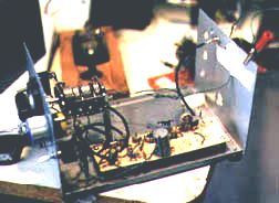
Construction: Use any method of construction that you prefer: dead bug, point-to-point, vector board, etc; I used my usual experimenter's circuit board. Keep all leads short as possible and, if possible, use RG174 miniature coax for runs that carry RF out to offboard components. Put the crystal holder (or board-mounted crystals switched with a rotary switch) close to C1.
If your station setup doesn't have a filtered keyed-out +V capability from a Station Controller or similar device, the transmitter will also need a KEYING SWITCH such as the one depicted below.

According to original source W1FB (see below), this transmitter also works as a 10-meter transmitter with no changes other than using 10-meter crystals instead of 15-meter crystals.
Inexpensive kits of non-VXO "Little Joe" transmitters are available from Dans Small Parts. The versions for frequencies lower than 20 meters put out better than one watt; only the 15/10 meter version requires the oscillator to run continuously to prevent chirp.
There are plans for a somewhat more complex, but still easy-to build 3-watt 15-meter VXO transmitter on AA3SJ's website here that does not require the oscillator to run throughout the transmit period.
..need parts?...
Sources:
American Radio Relay League
      "A VXO-Controlled CW Transmitter for 3.5 to 21 MHz";
           ARRL HANDBOOK, 1991 ed.(Newington, CT) pp.30-27 thru 30-29.

"Experimenting for the Beginner," by Doug DeMaw W1FB
     QST (September 1981) pp.13-14.

Plans for non-VXO "Little Joe" Universal QRP Transmitters also appear
in QRP Classics (page 9) and Solid State Design.