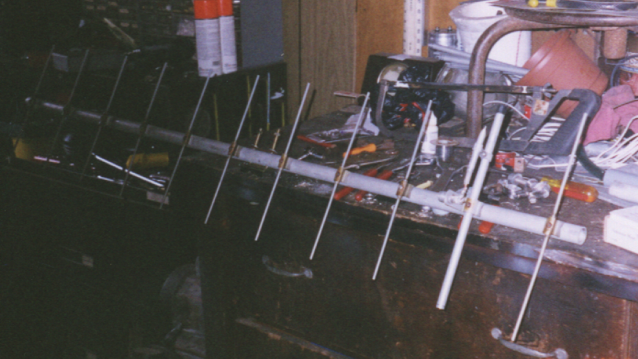
In addition, I'm looking for a set of OSCAR beams
that will eventually replace my home station and leave the existing
array for portable work. A 160W amplifier will also be added
later on as required, although it has not been needed so far. The
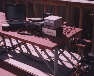
40-45W's of output that my IC-821H has has been more than adequate in
making contacts over 8,000
nm "round trip".
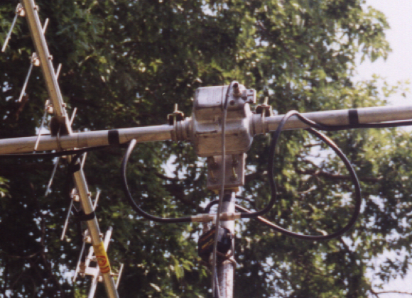
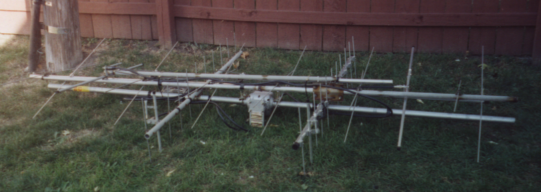
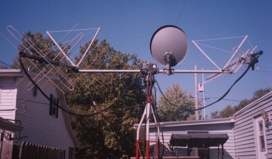
Thanks to Jerry W0SAT and Bill N9JWO, I have acquired KLM's 2M-14C and
435-40CX antennas that will replace my current Satellite array some
time in the next month or so. I have also acquired a TAPR TrakBox and a
Kenpro KR-5400A dual control antenna rotor.
My KLM's are up and running, ready for Field day
tests.
I have rebuilt the relay box and it works great. Working on the
TrackBox
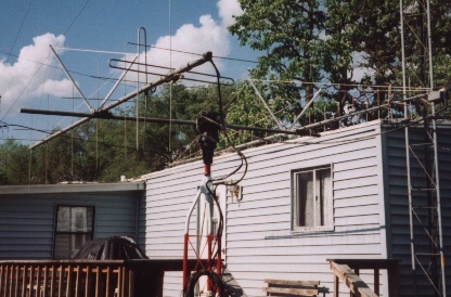
interface to automate the tracking. After Field day the system will
replace
the current antenna system placed 30ft. up to clear obstacles.
Update:
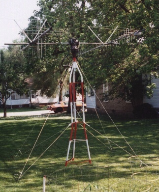
My KLM'S have been modified with a 1 1/2" metal cross mast cut to six foot.
The beams are turned 45 deg. to limit the interaction with the mast. Tests show
little to no change in performance of the setup.
Still working with the Trackbox to get the unit to track as a stand-alone unit.
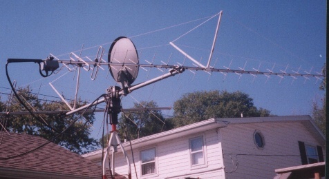
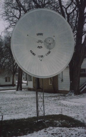
AO-40 Dish Project:
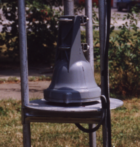
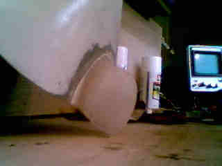
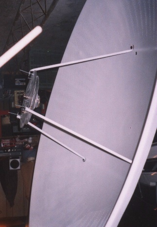
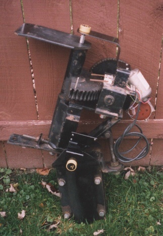
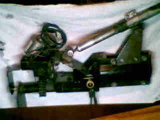
Oct. 26, 2003. Today I accuired an eight foot dish assembly to convert over for use
with AO-40. The dish is aluminium with all steel mount. The assembly has horizon to horizon
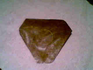
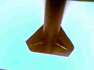
AZ motor and set bolt for EL which will be converted to a screw system for EL. The Patch
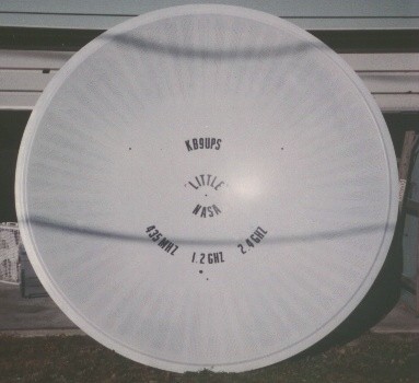
feed will be a Tri-band for S, L, and U (435MHz, 1269MHz and 2401MHz CP). The down converter
will be Bob's/k5gna AIDC3731AA which seems to be the best choice I've found. Potentiometers used
for this project are from Allied Electronics (1-800-433-5700) p/n 970-1680; 132-0-0-103: 1 turn
10K .5% linearity.
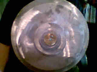
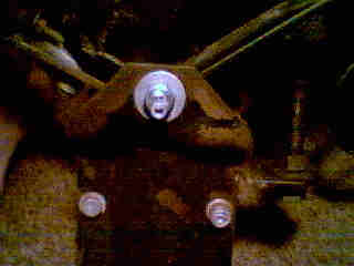
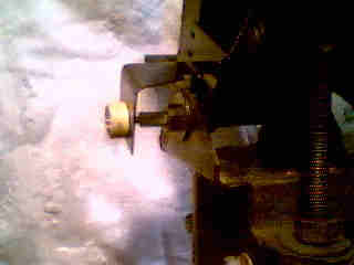
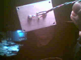
Potentiometer Mounts:
I used two threaded rod addaptors one inch long, 1/4 x 3/8. I drilled out the 1/4" end for the
potentiometer shaft and drilled a 6/32 hole for a set-screw. I cut a one inch long piece of 3/8
threaded rod to connect the addaptor to the mount. The AZ potentiometer is placed at the top of
the mount on the center axis. "3/8-16" hole drilled and tapped to hold the addaptor. The bracket
made from 1/8 x 3" stock formed to mount to the sheild bracket as to be flexable for any offset of
centers. The EL potentiometer is mounted at the pivit bolt center. The addaptor is made the same as
AZ. I drilled and tapped a 3/8-16 hole in the center of the bolt. The bracket is mounted on the upper
part of the mount and formed to rotate over the center axis.
(The AZ potentiometer is stationary, the
EL potentiometer rotates about its axis).
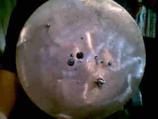
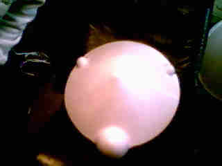
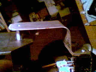
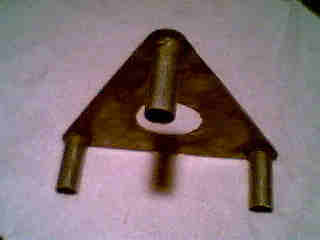
Mast Mounts & Dish Support:
Supports for the 3 1/3" mast are held in place by two plates. "Top" assembled to fit over one section
of Rohn-25 tower. "Bottom" fit inside the tower section so that it will help support dish weight. Mast
is 3 1/2" dia. 1/4" wall, cut to 54" and is welded at top only. This makes the assembly "removalbe"
leaving only the tower section in the ground. The bottom plate will have three flanges for centering of
and stabilization of the mast.
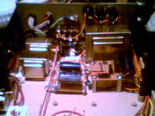
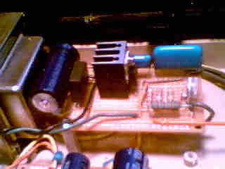
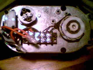
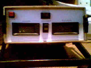
Controler Power:
Power Supply for the dish motors are one 25vdc supply. The motor supply is adjustable for fine
tunning motor voltage. There will be two 12vdc supplies, one for potentiometers and one for the
displays.
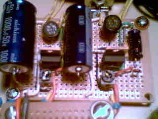
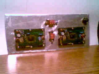
The motor board is regulated and filtered with a 2200uF 50v cap. The pot/display power board is also
regulated and adjustable, filtered with one 1000uF 35v cap and one 1000uF 50v cap. The cap's would have
been the same, but where not availible. The motor supply is set at 18.5vdc.
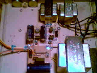
Motor board update:
Testing the board proved that the original components where to light to handle the
current, so upgrading the board was needed. I have added a current boost circuit that concists of a
heatsinked 2N3055 in parallel with the LM317T regulator. This has taken all the heat off of the LM317T,
it seems to be helping. Also added a heatsink to the LM317T regulator. There is a 1W 1.2K bleed-off
resistor between the positive and negitive output leads. Temps now within exceptable range
and working great.
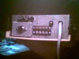
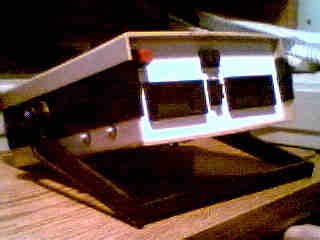
Displays & Switches:
The switches are Allied #676-0035 rocker type DPDT. Power will be on center and motor on each end
reversing polarity from one to the other, (+,-)(-,+). The DPM's (digital power meters)are Jameco
#970-1680 and are backlit. Calibration will be through a 10K pot and voltage divider using a 2.2M
resistor.
The face plate is made from two pieces of 1/16" alum. glued together. The labeling is printed on vinyl,
(shelf liner). I laid out the templete in "word" for printing. The vinyl was then put onto a standard
piece of printer paper, cut to fit, and run through the printer. The vinyl was then removed from the
paper and with the adhesive backing placed onto the alum. plate. Switches and displays then mounted.
Voltage dividers:
The voltage dividers have been changed from Roberts posted values to match my design. R1 still remains
at 2.2m ohms but the R2 has been changed to 6620ohms. This makes the change from the 3v (180deg AZ)
setting to the required 18mv needed for the displays. On the displays, RA had to be removed so that the
displays would read out in mv. The high end pots are 10K and mounted on the side of the cabinet for both
AZ and EL adjustments.
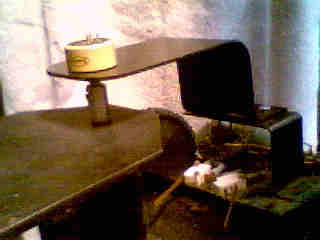
Final Project Assembly:
With minor adjustments still to preform, setup has begun. As of December 14, 2003 the motor assembly
has been placed on its mount. The dish is being assembled and made ready to be mounted. Hope to have the
down converter sometime mid January and ready for tests late January.
Dish assembly has been mounted and the tuning and calibration has begun. Focal point has been set at
29.38", (dish to 435MHz reflector plate). The 435MHz patch SWR tuned up to 1.3:1, best I could get.
Dish Project Up and Runing:
With the downconverter installed on January 12, testing confurmed all is good to go for the first signal
to come in. Power up showed a noise floor of S3-4, AO-40's beacon came in at S9+5.
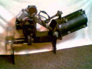
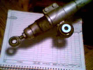
Dish Status & Drive unit Update:
With AO-40 out of the picture for now, I've decided to re-design the AZ drive unit to get true AZ/EL
opperation. The refit will consist of a seperate drive motor and gear reduction system including a sensor
for AZ readout. This unit will turn the entire dish assembley so to cancel out the arch of the horizon
to horizon movement of the original unit. The EL assembley will remain the same with one modification
in that it will have extended range providing movement from 0-90 deg. The design, fabrication and assembley
is expected to be complete in four months. Details can be seen on my Station 2 page.