8' Dish drive and 12' Dish project
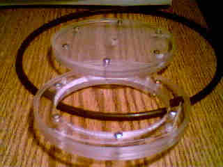
Dish Drive Unit:
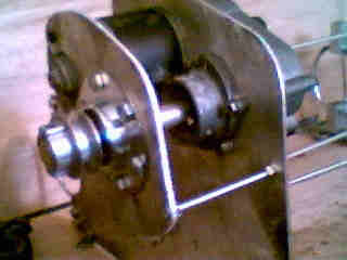
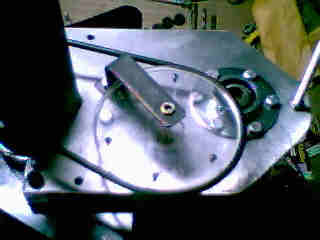
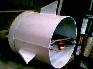
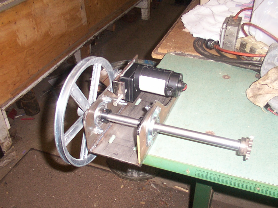
Drive prototype works good. Now, I can rebuild the plates with 1/4" steel.

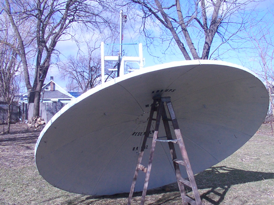
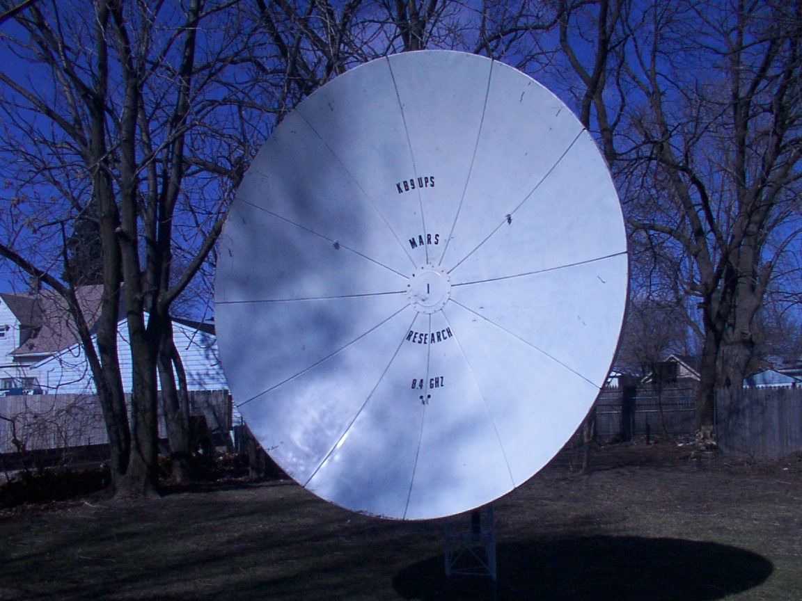
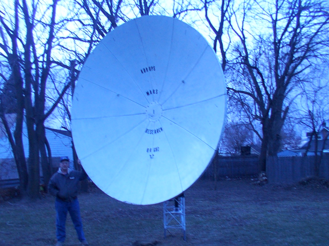
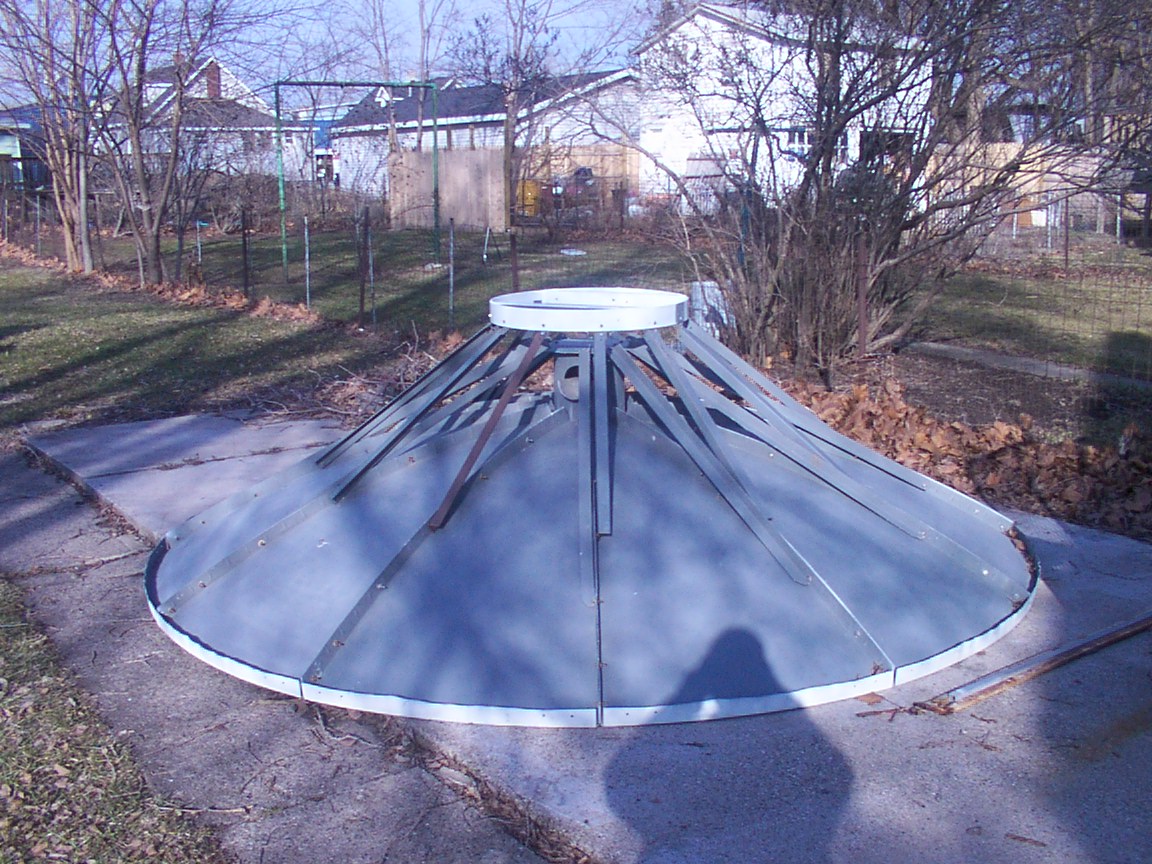
12' Dish Project:
The 12' dish acquired in Ohio will also be fitted with a tri-band patch, but it will also have a second
feed attachment for 8.4GHz to recieve tlm from the Mars probe. 5.4GHz is also being concidered.
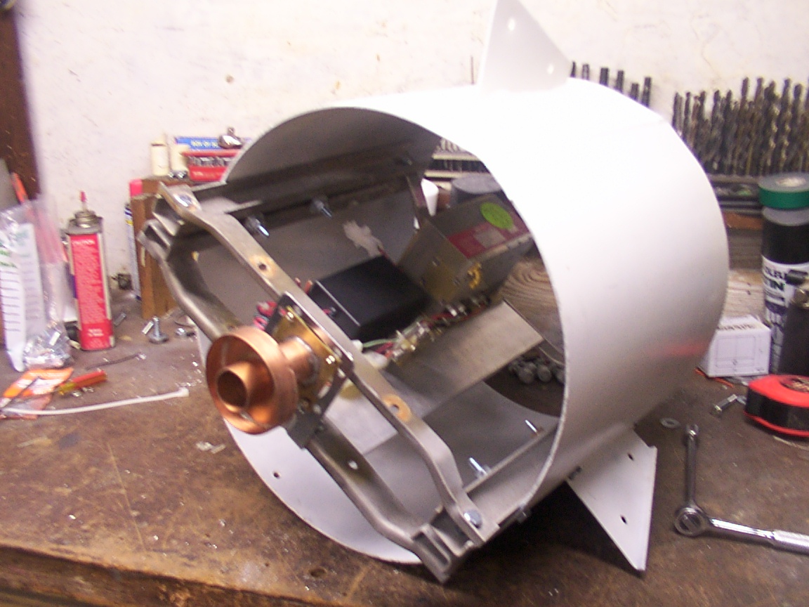
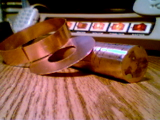
The Mars probes have been on my mind for some time now and the opertunity made itself visible just recently. So along with the re-build of the 12' dish for EME, I plan to add the feed for 8.4GHz (8406.8519MHz and 8420.4321MHz) in one pipe feed.
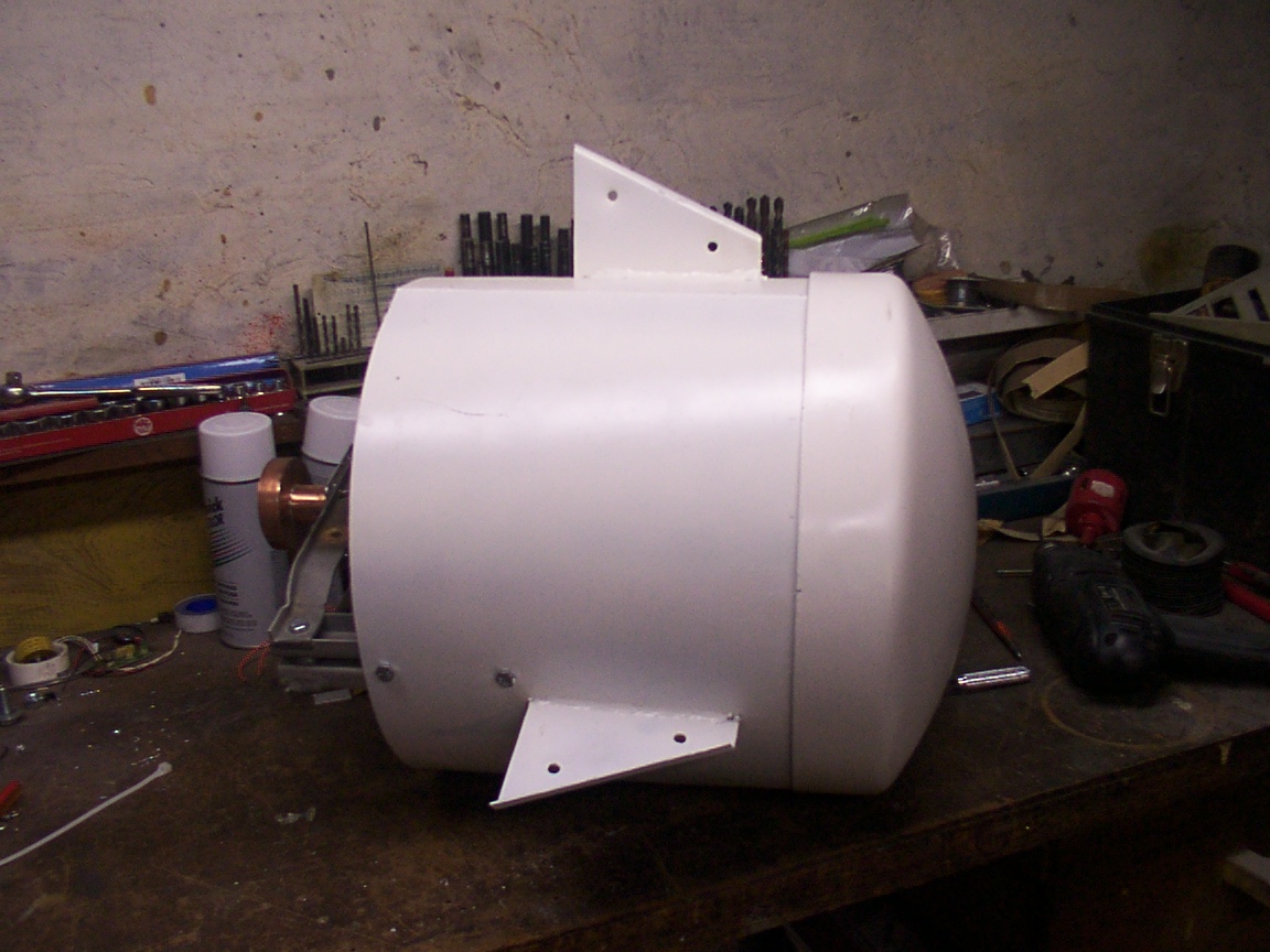
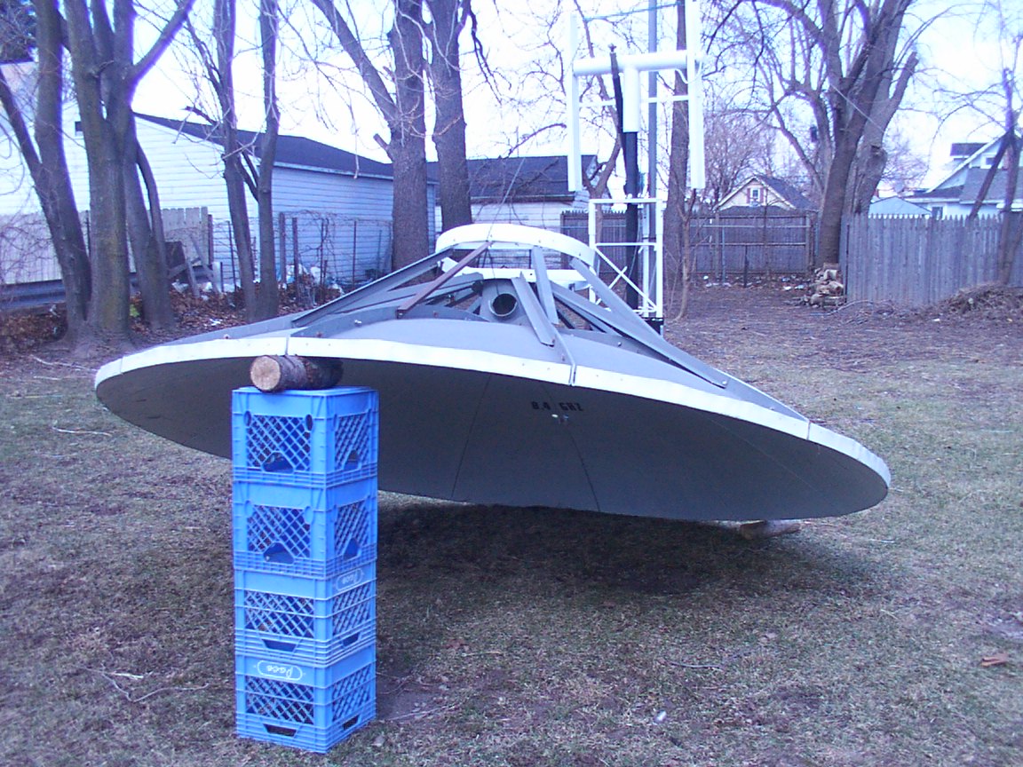
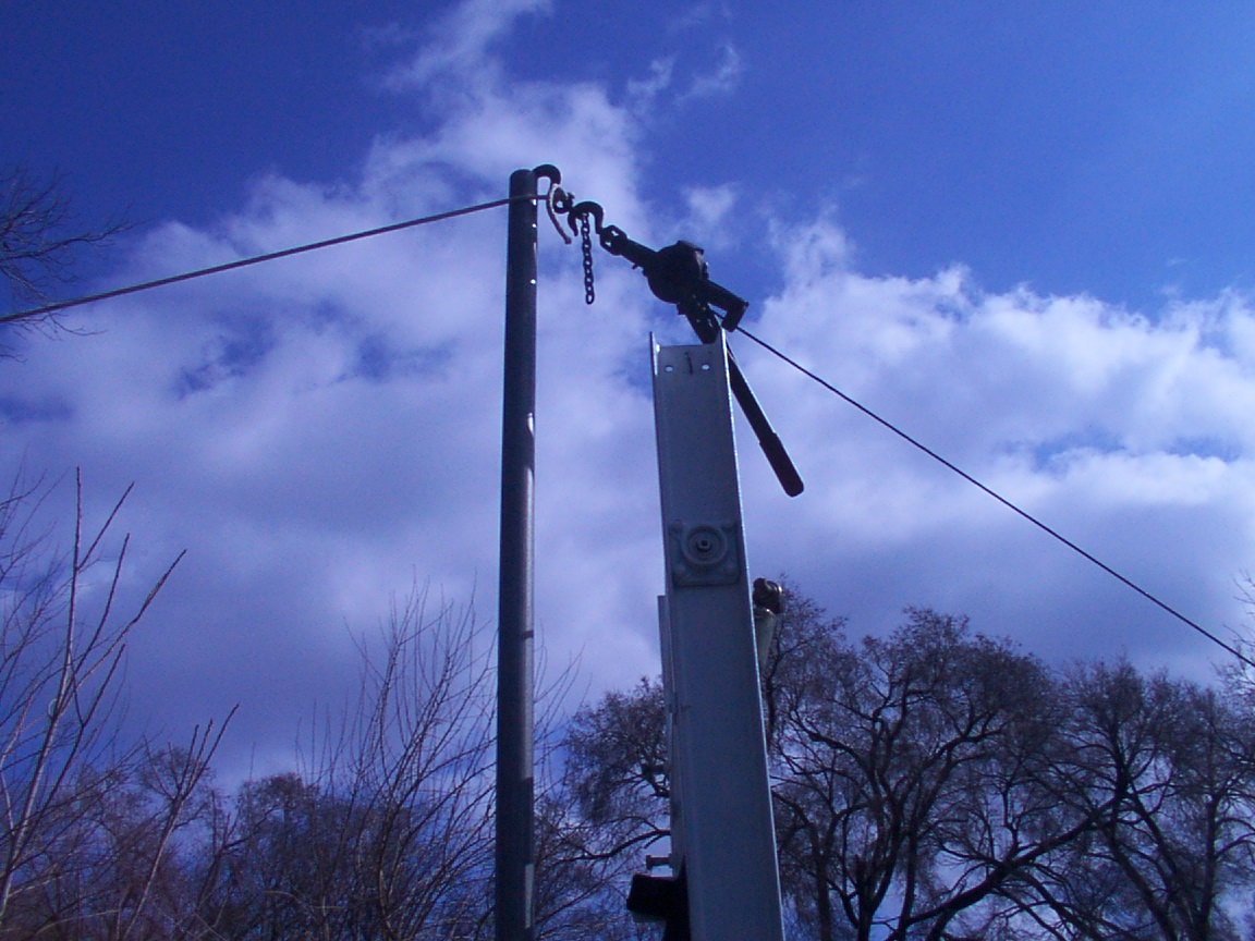
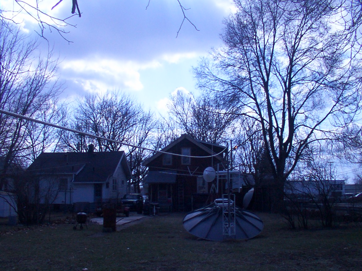
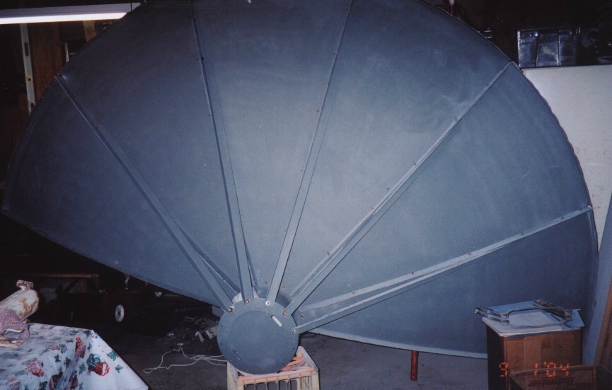
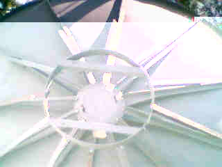
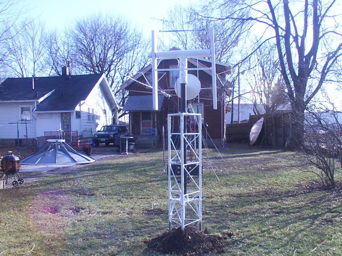
The 12' dish has been repainted and reassembled. Next is the mount assembly.
8.4GHz Mars Express & Odyssey Project:
The Mars probes have been on my mind for some time now and the opertunity made itself visible just recently. So along with the re-build of the 12' dish for EME, I plan to add the feed for 8.4GHz (8406.8519MHz and 8420.4321MHz) in one pipe feed.
The 12' dish has been repainted and reassembled. Next is the mount assembly.

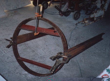
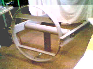
12' Dish Mount Sketch
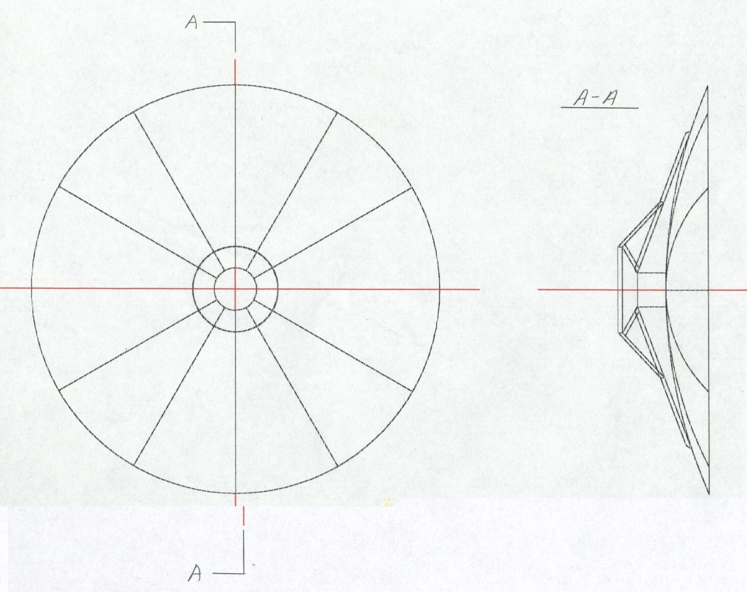
The mount adapter ring is made from 1/4" x 3" steel and was formed by chaining it to the wheel of my Jeep
and backing over it forming it into a ring just about the right size. Then the two cross pieces of angle
could be fit and welded as the ring was formed and welded together. Using 1/8" x 1 1/2" flat stock 12 brackets
where made and bent to near 45 deg. to attach the "bed frame" support angles from the ring to dish.
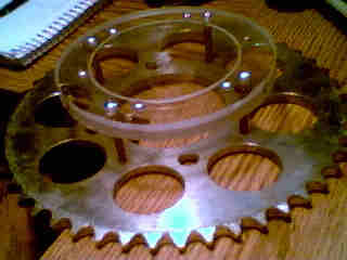
The "C" rails are 4" and have a 3/4" bearing flange for elevation.
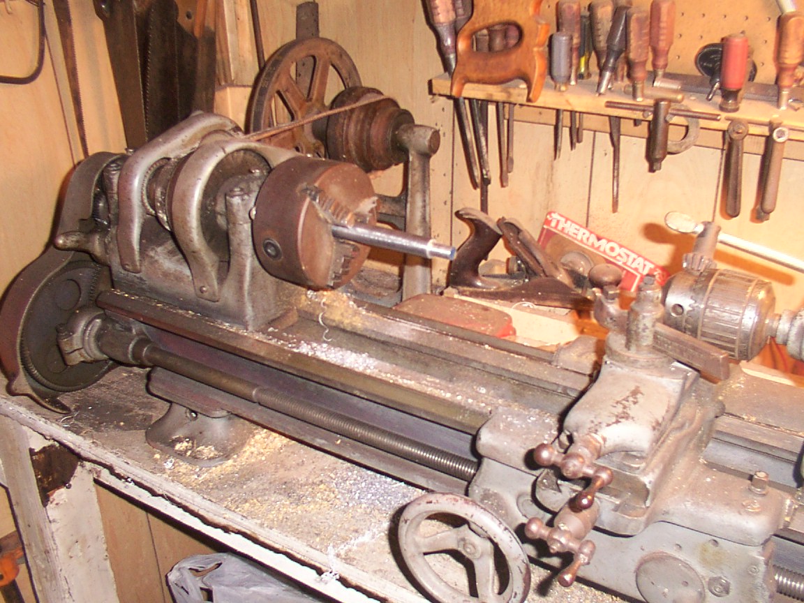
Elevation frame ends are one piece turned to size and welded in place.
Elevation frame ends are one piece turned to size and welded in place.
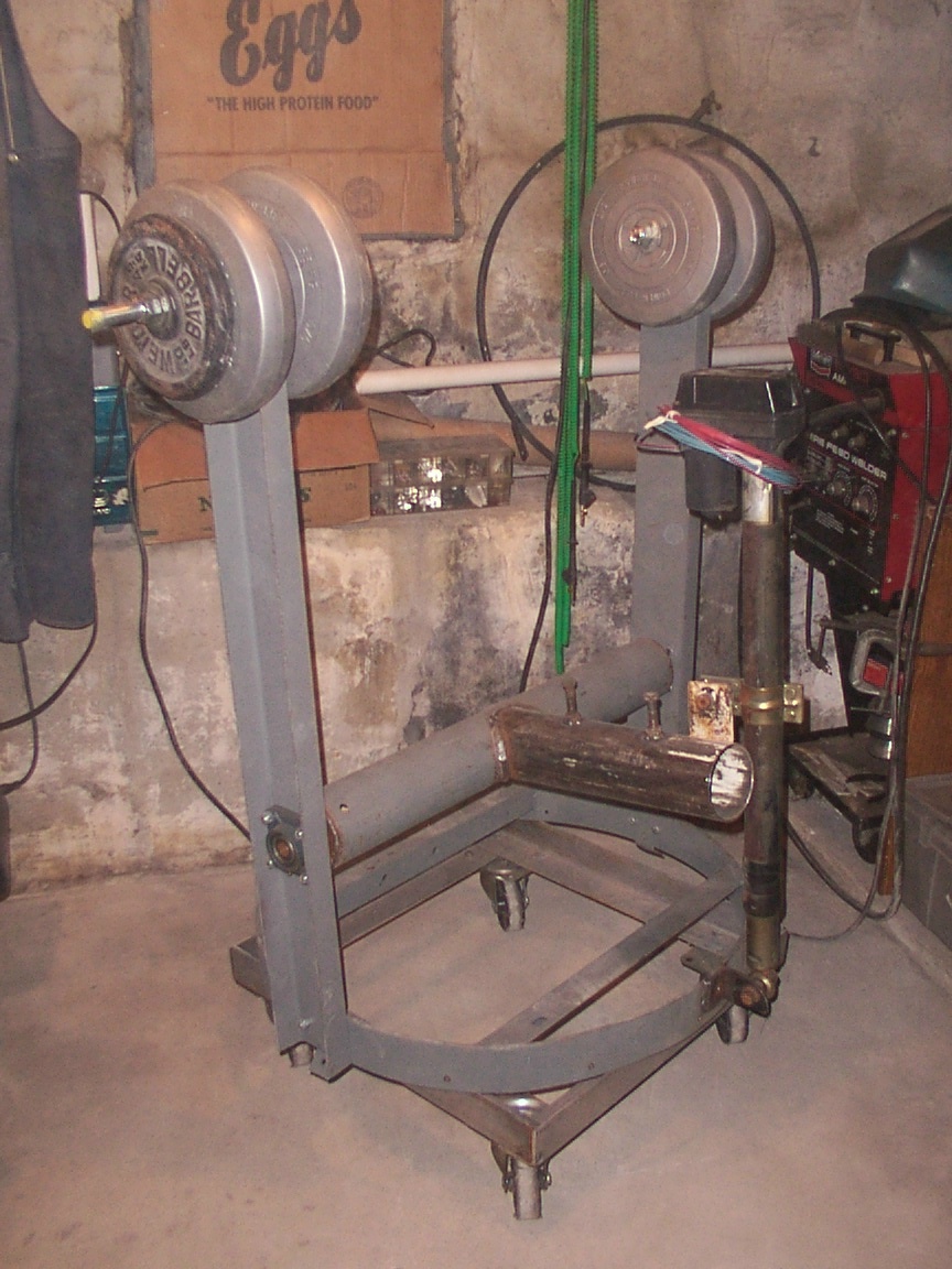
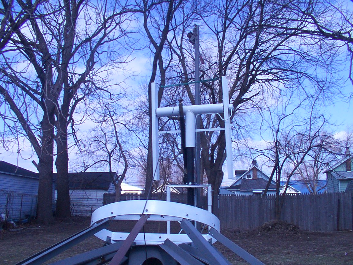
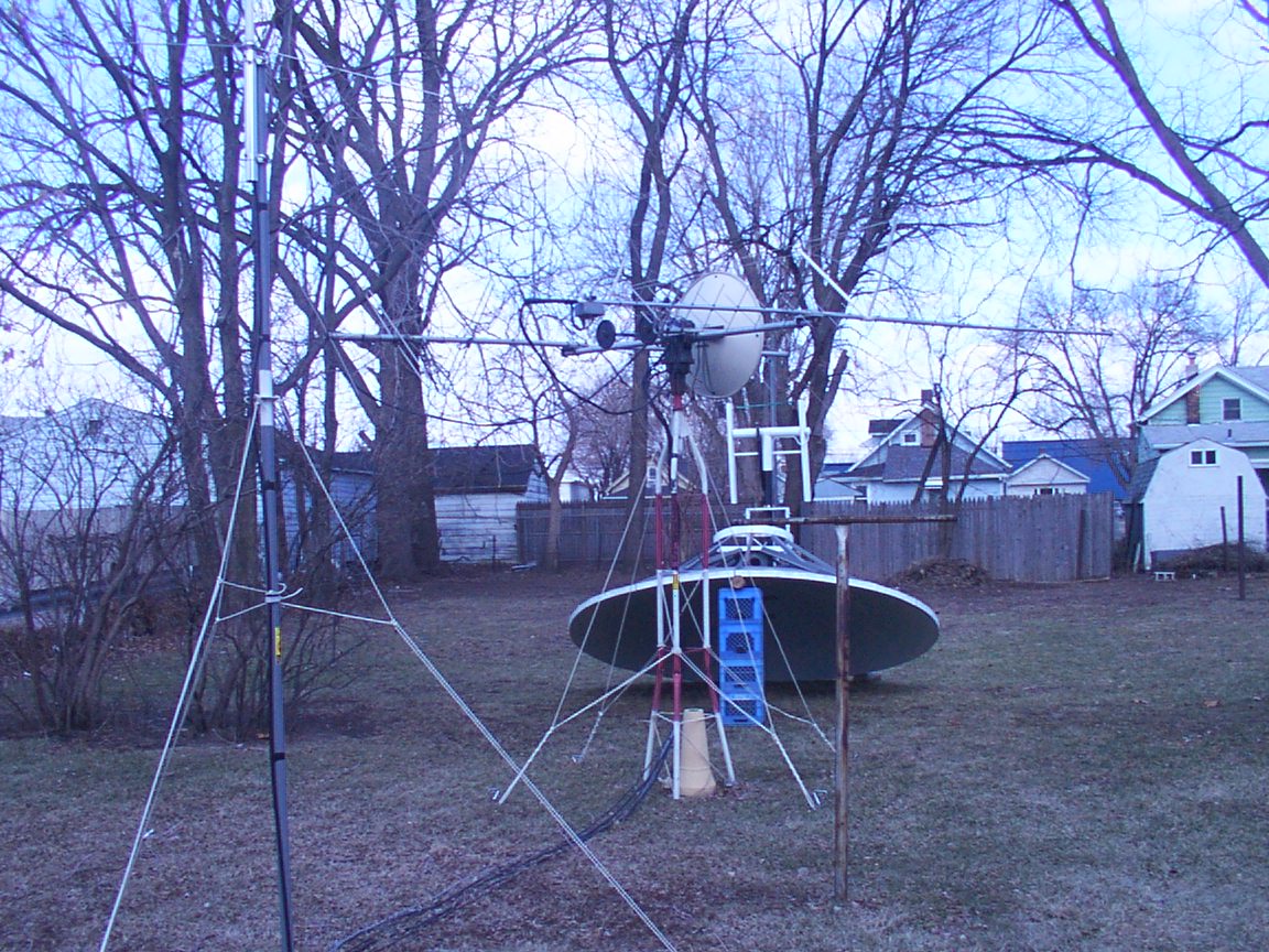
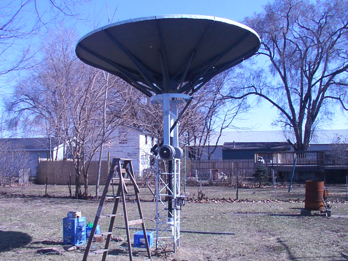
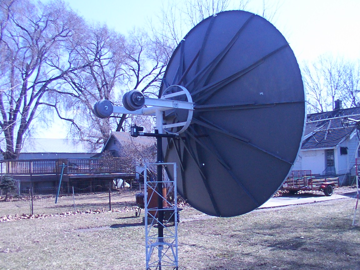
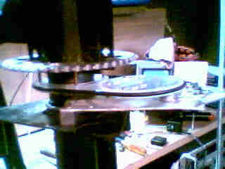
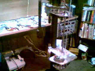
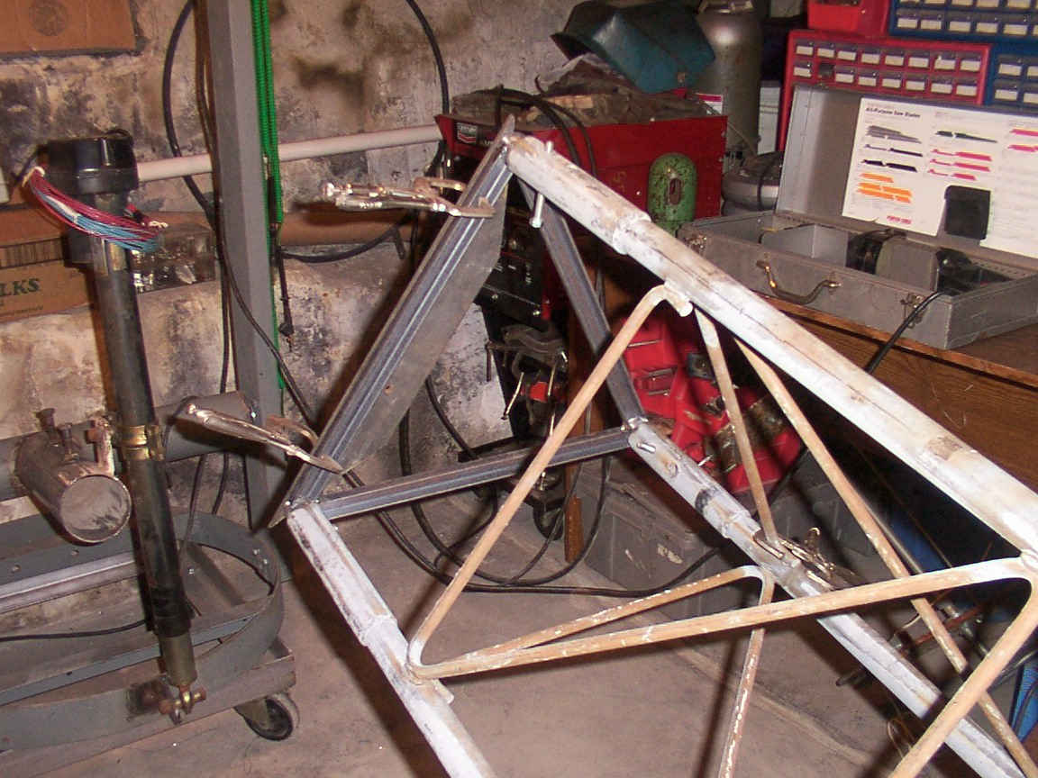
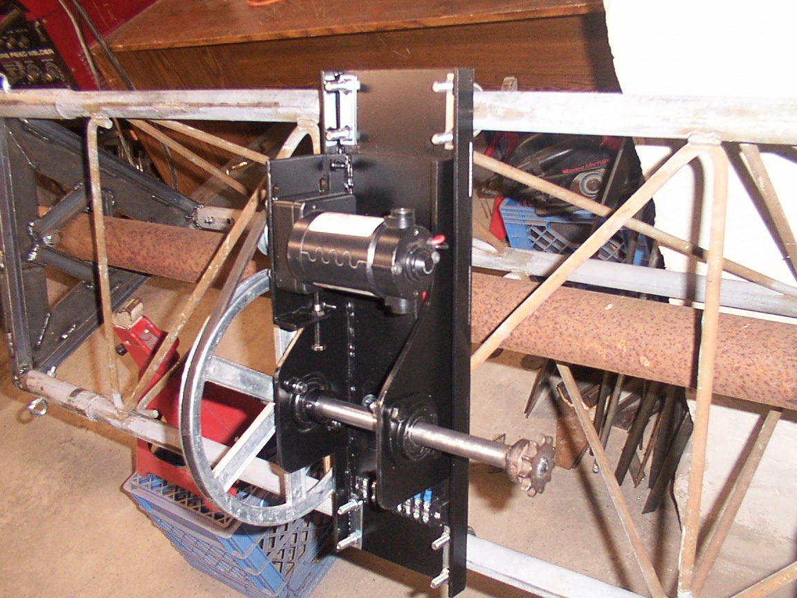
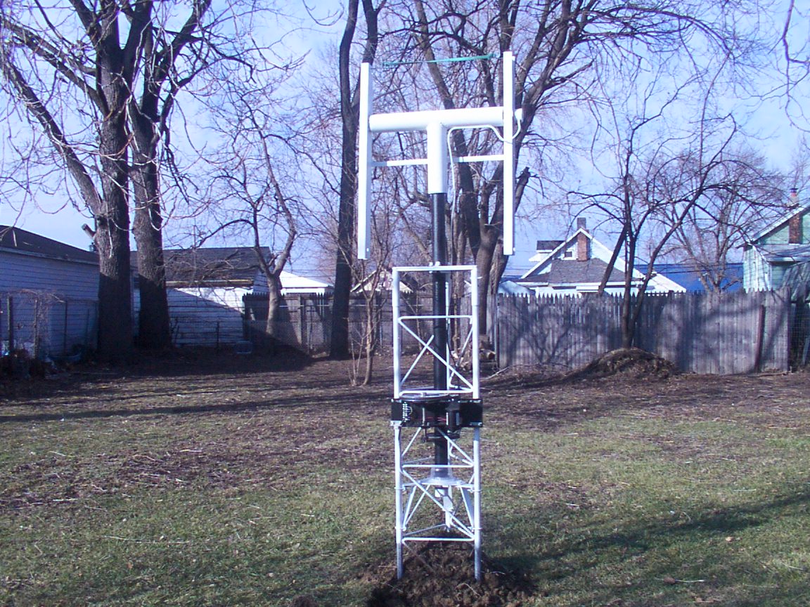
12' Dish Mount Assembly
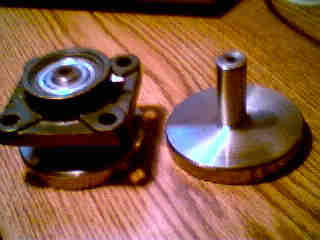
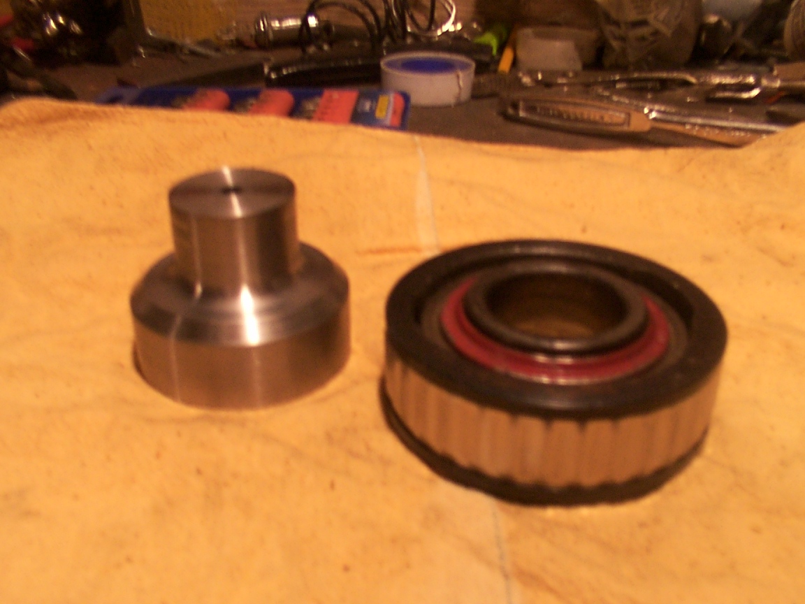
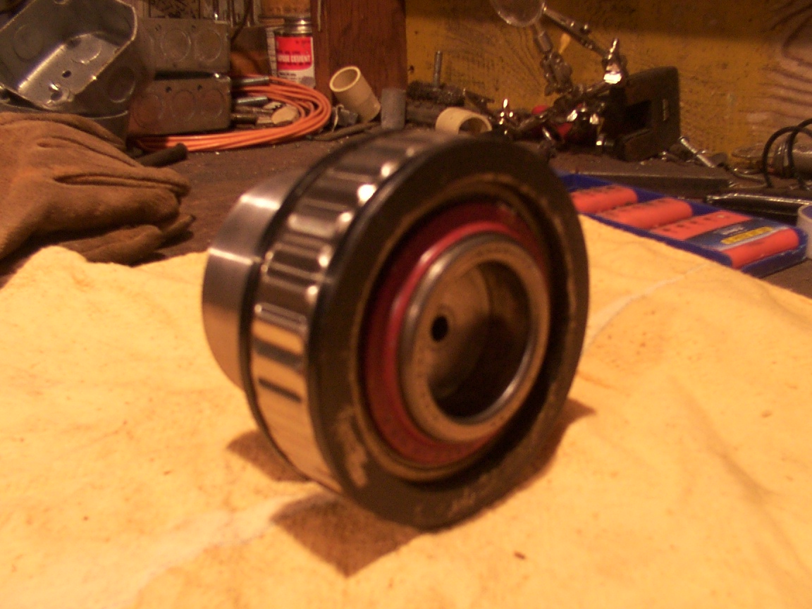
My mount comes from a collection of three other desines that I have found. Most of the parts have been found at scrap yards and others
are parts from other projects like my AZ drive bearing. It came from my dad's boat. It's an out dirve shaft bearing. The tower section
is a Rohn 45G and came from Bill / ka9fer in Il.
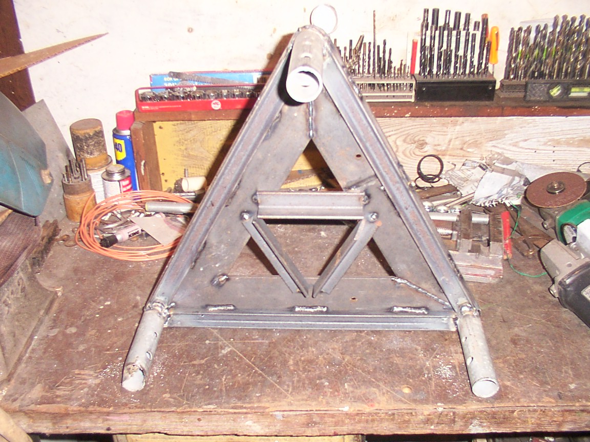
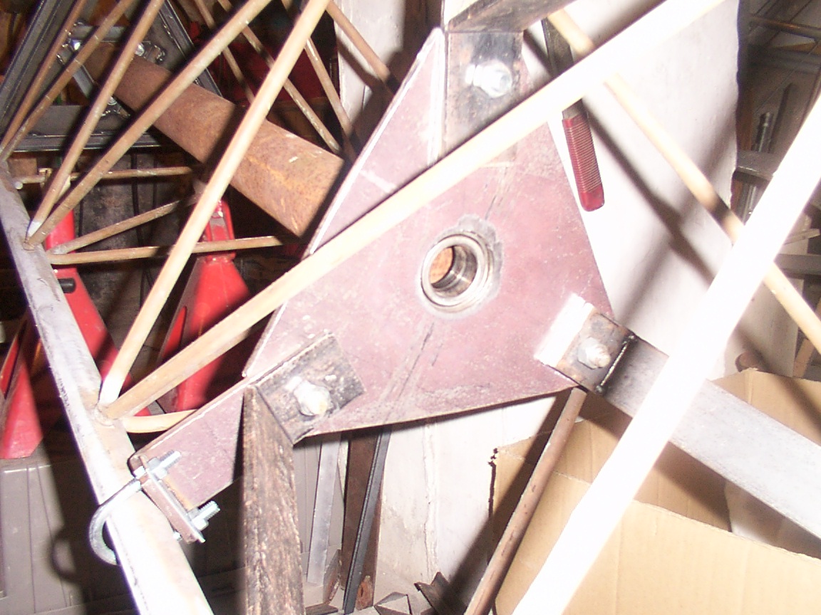
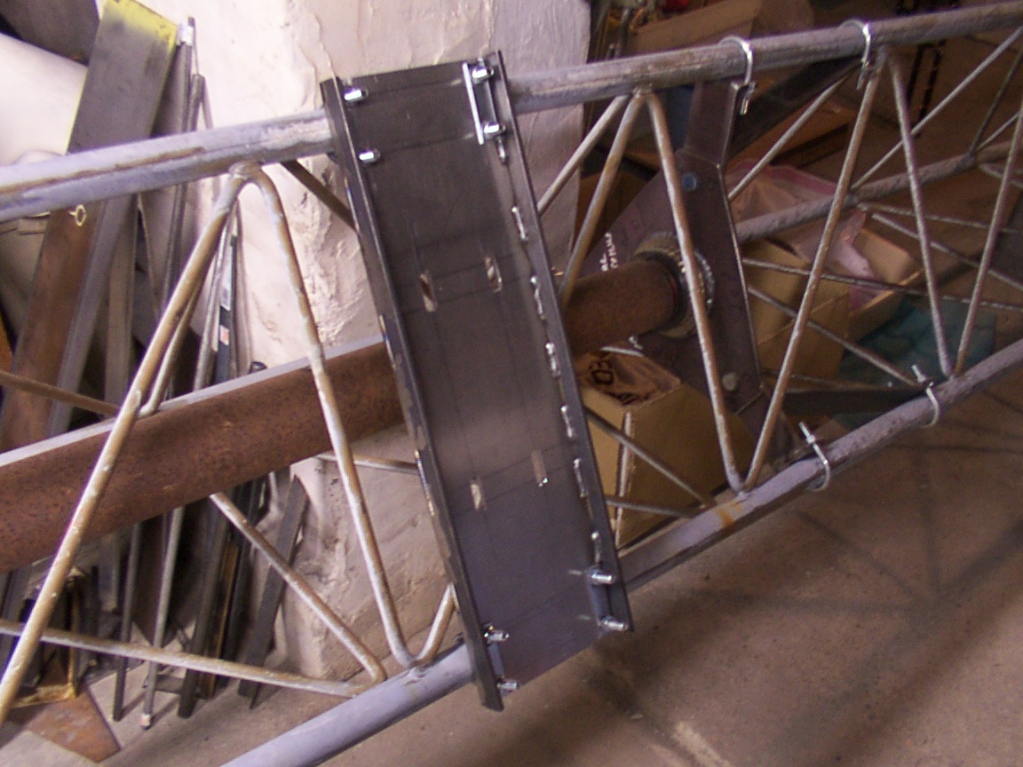
Nut's & Bolts of It
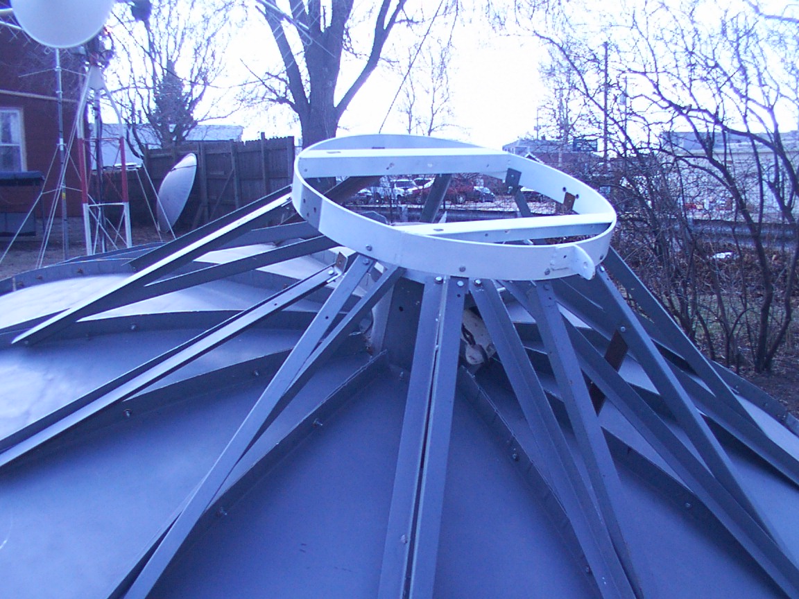
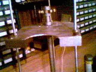
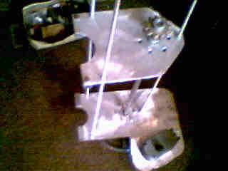
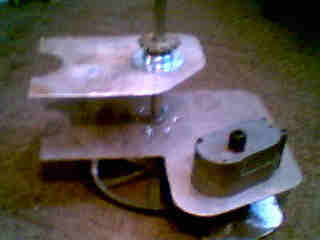
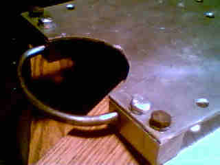
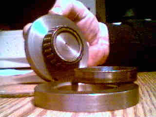
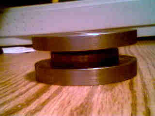
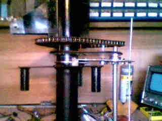
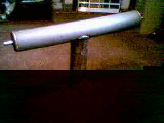
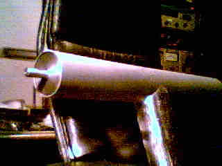
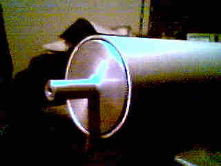
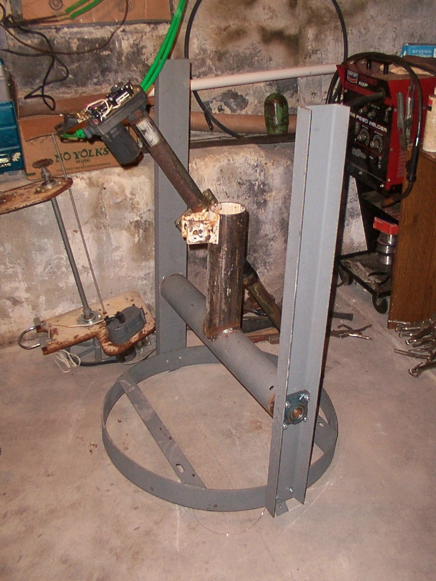
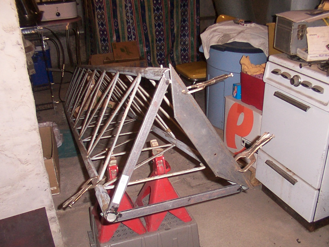
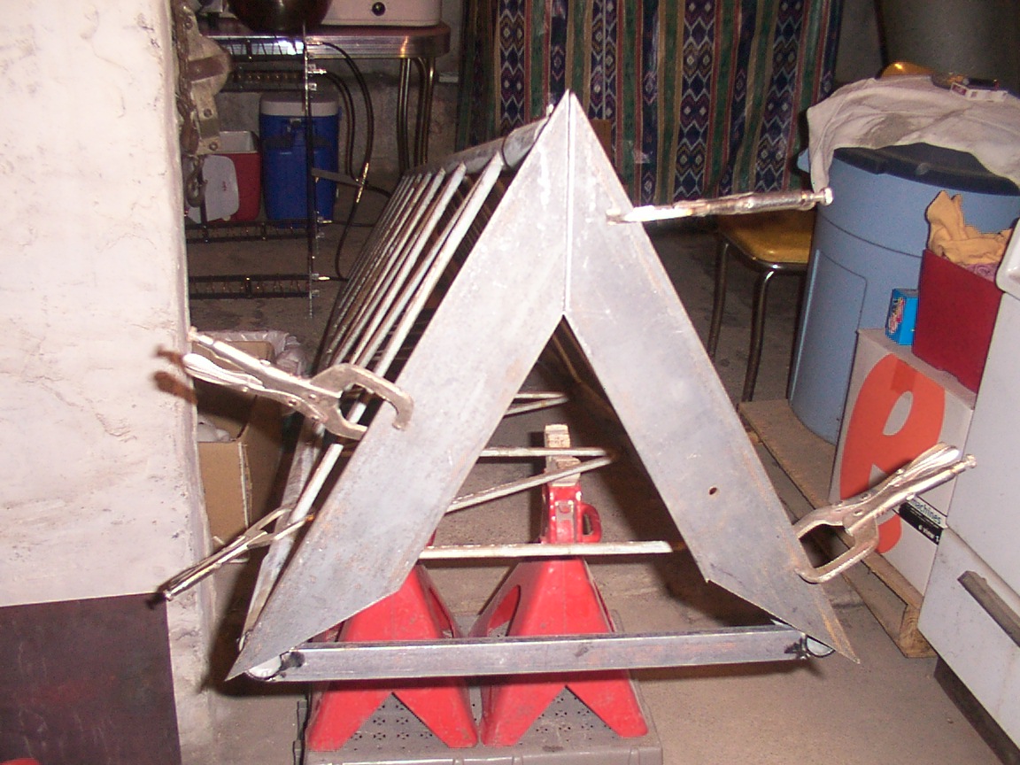
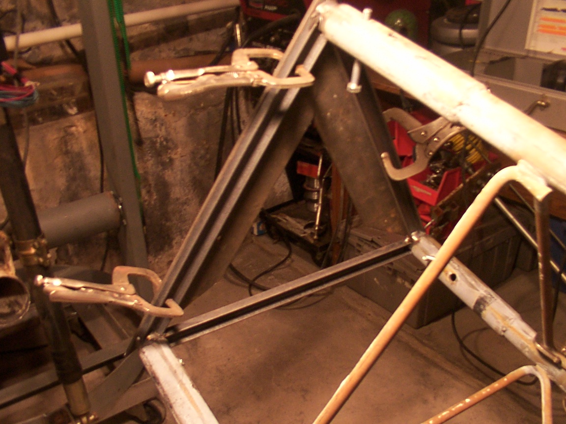
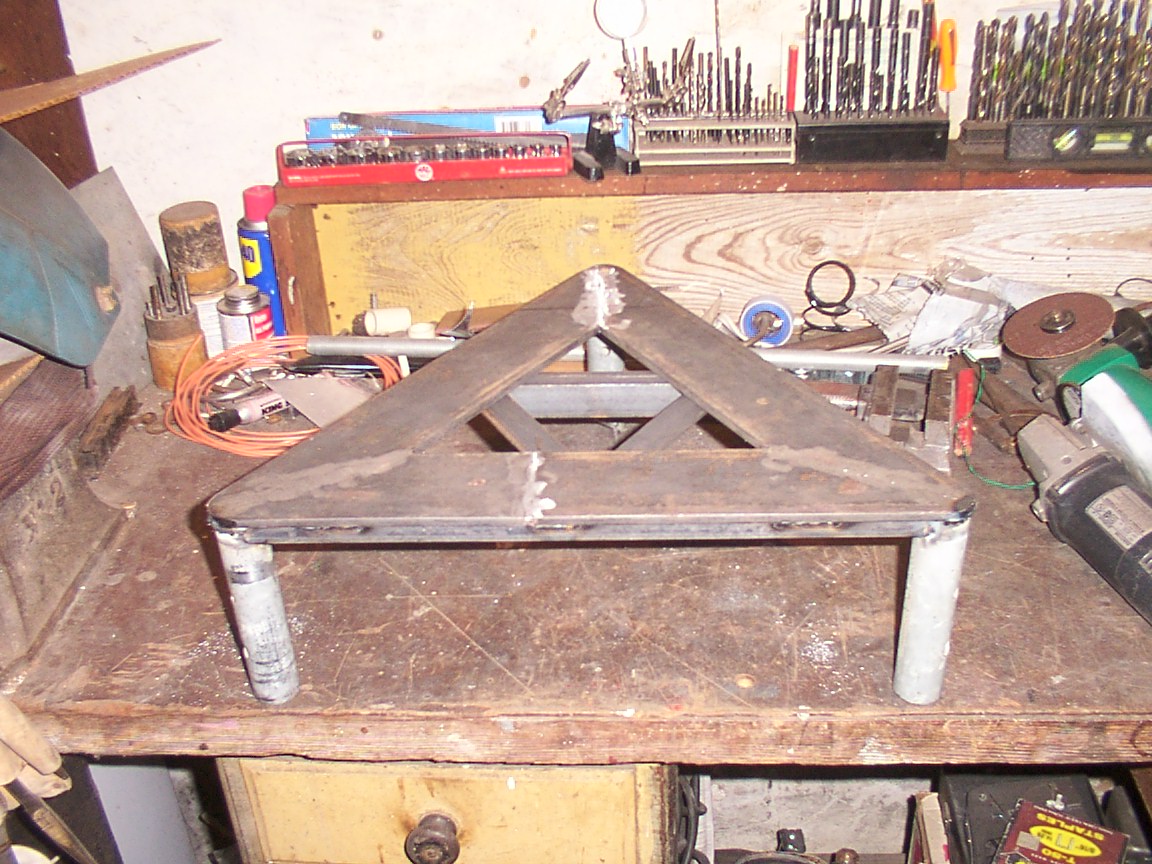
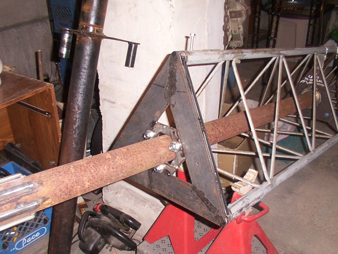
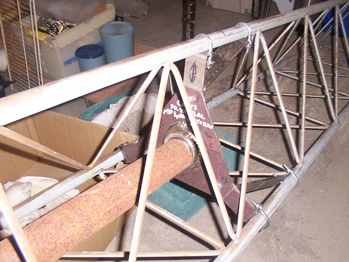
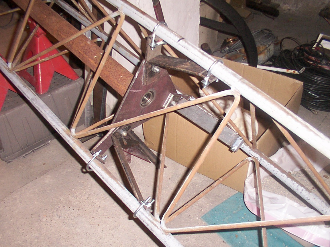
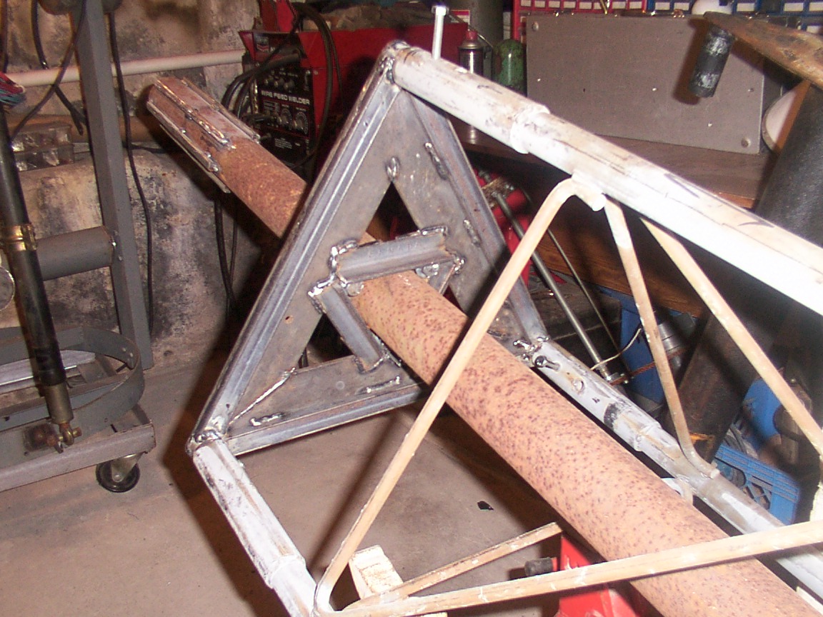
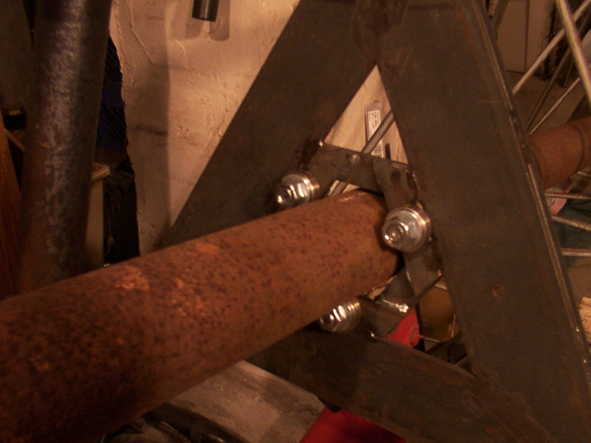
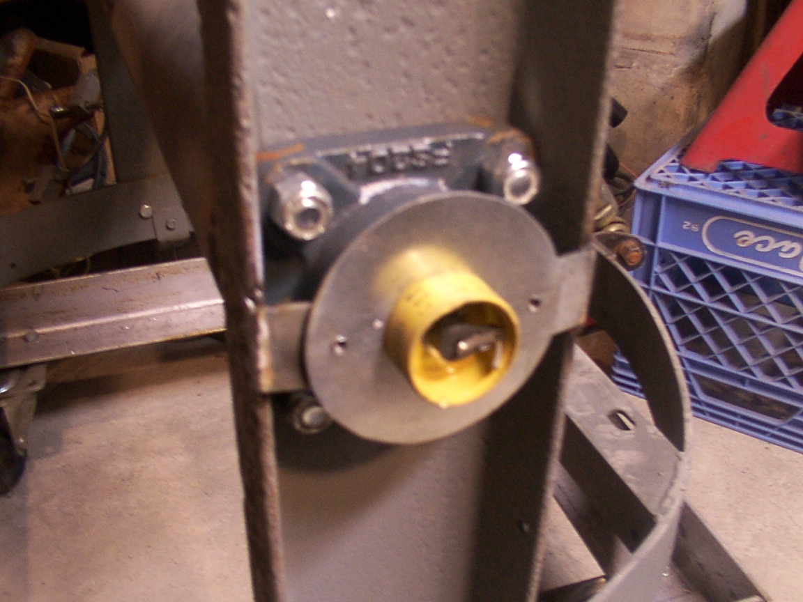
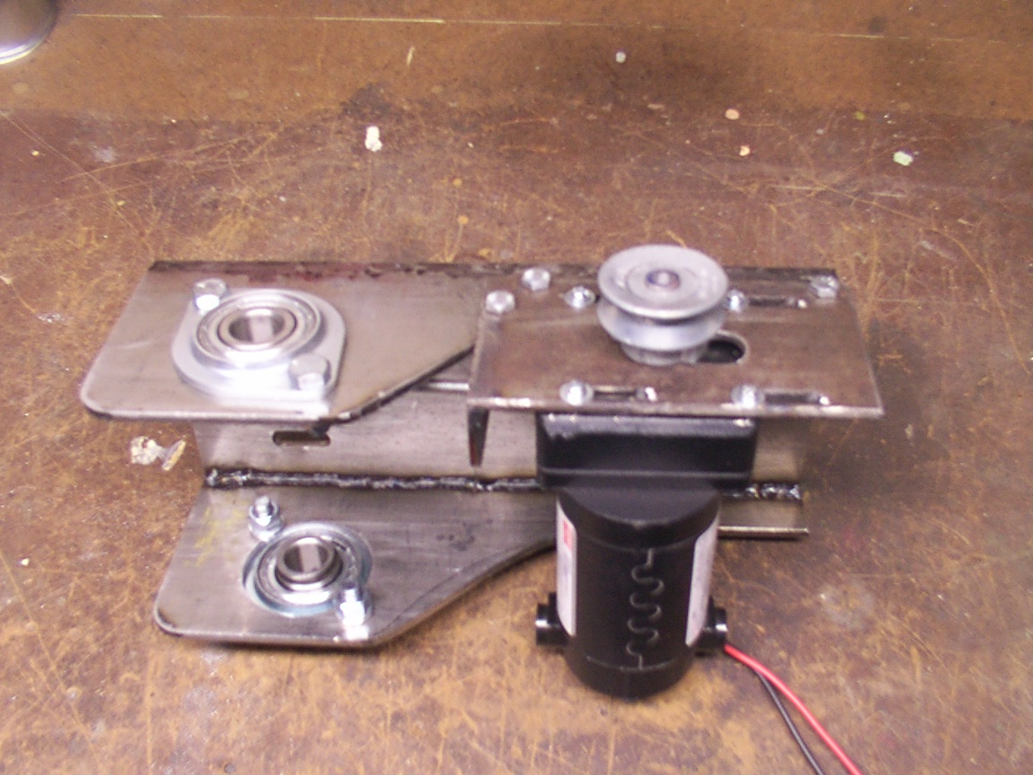
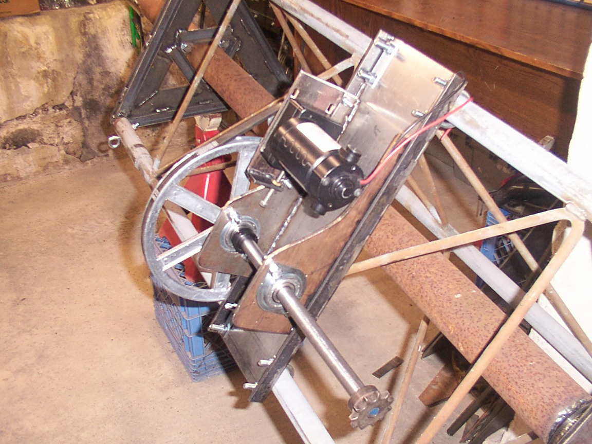
Cutting off the three male ends of the tower and inserting them into the opposit end lining up the bolt holes and leaving about 1" of tube extending out from the female end. Then fitting 1" "C" channel between the three posts which tied the three together. Then cutting three plates of 1/4" x 3", welded over the channel to form the triangle deck. To further center the 3" thick wall pipe AZ drive shaft, three 1" angle iron was welded between the points on the under side closing the space on three points to just at 3". Adding three 1/4"x 1" pieces on top to hold the 3, 1/2" bolts and ball bearings for final support of the drive shaft. The three support bearings are pressed over the three 1/2" x 1 1/4" bolts with a flat washer on both sides of the bearing and a locking nut. The bearings spaced just touching the shaft.
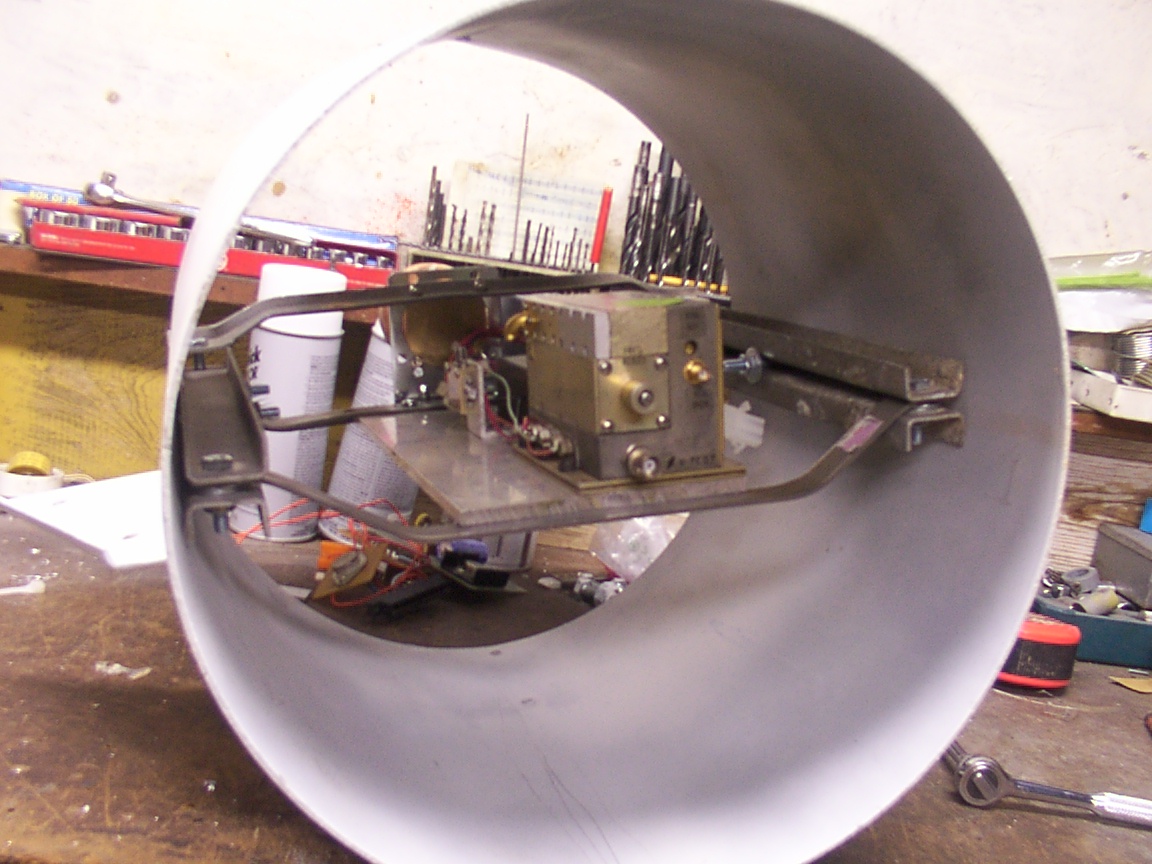
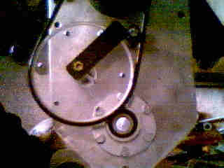
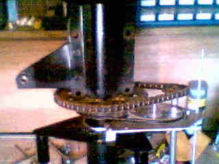
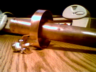
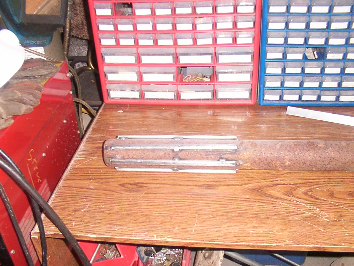
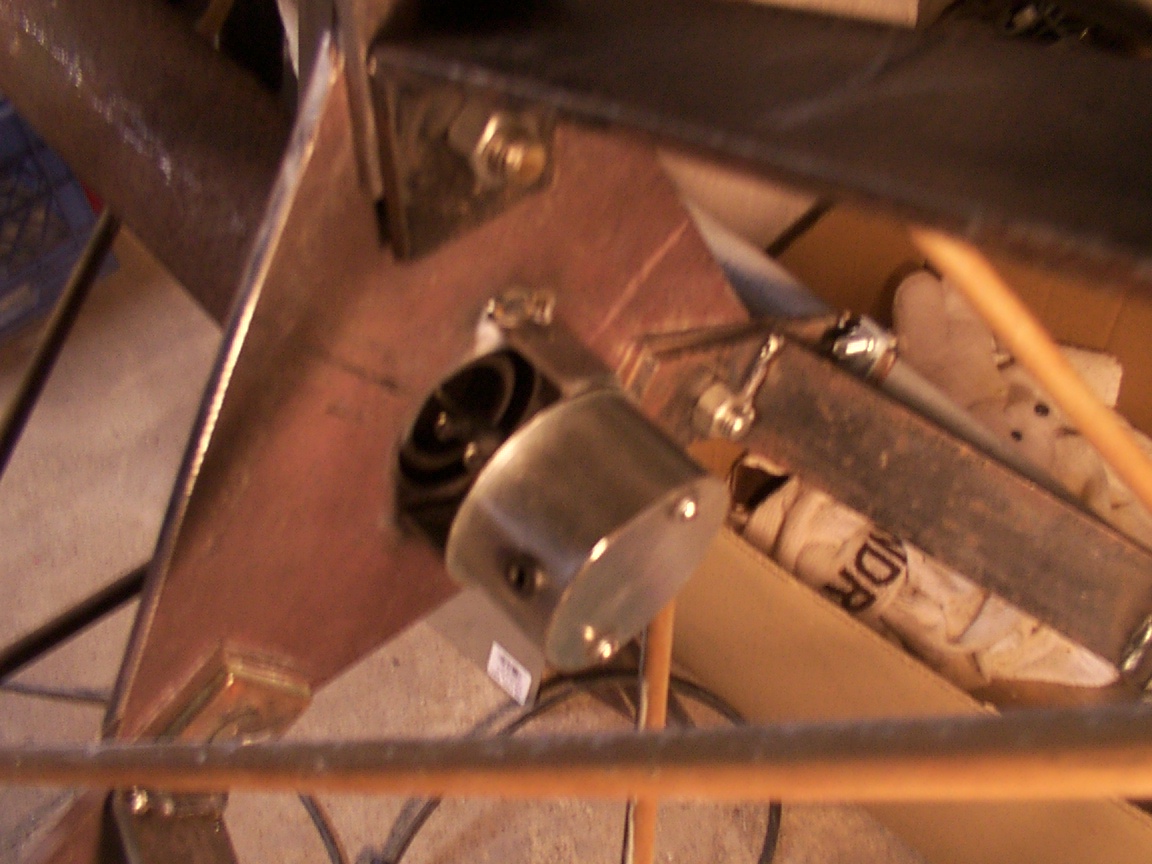
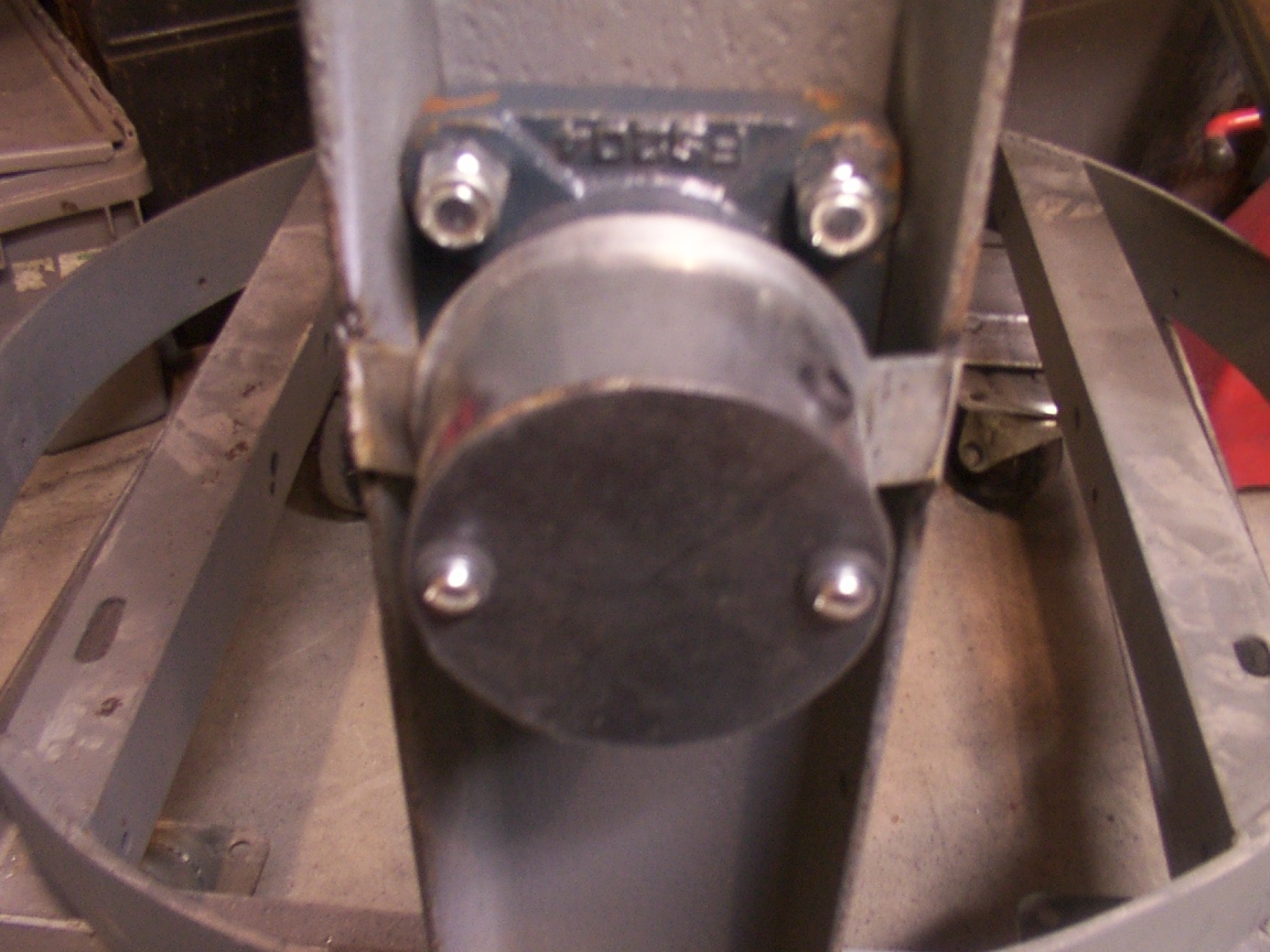
As seen in picture (2), I cut six 1/2" x 12" rods and welded them evenly spaced around the drive pipe as it is smaller than needed to fit the EL assembly. I cound not find the right dia pipe and again my dad had pleanty of 3" thick wall behind the barn. With a little grinding, it fit like a glove. I have two 1/2" tightening bolts and can add two more if its not stable, but don't see a problem yet. So far I have only had to farm out two jobs that I could not do here at home. First being the drive shaft end which my other half had several favors due, so the cost was "zip". Second was the 2 1/4" hole in the lower plate. This being 1/4" thick I didn't have any other way to cut it so I had it laser cut at a cost of $50. Only had to go one block north of the house to get it done. The drive bearing is held in place by a piece of 3/8" square stock bent into a circle using the drive pipe as a form, then tack welding it and forming it as I welded it to the plate. I need to mention that I do not have large tools or machines, I only use hand tools common to most "do it your selfers", other than the small mig welder, a tourch would be nice but I don't have one. The lower support arms are made of 1/4"x2" and to bend the tabbs I had to cut part way through then weld the cuts. The lower drive assembly is "U" bolted to the tower section and I will add a beed of weld under the bolts to keep the assembly from sliding down over time.
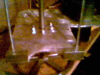
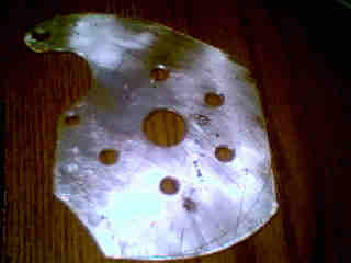
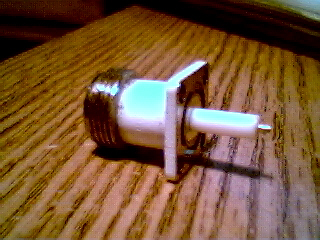
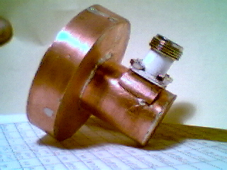
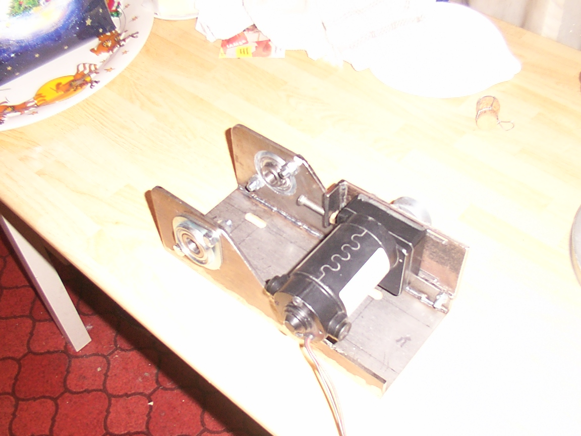
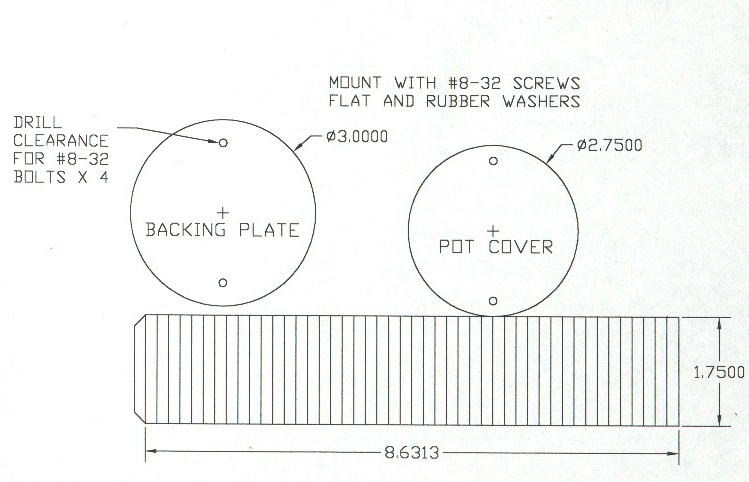
Potentiometer Mounts & Covers
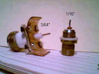
The brackets themselves are 3/16" x 1" steel bent to fit and drilled to mount the pots. The pots used are the same as the 8' dish project and are Model 132, Stock # 970-1680, Mfr.'s Type132-0-0-103 Wirewound Single-turn pots from Allied Electronics, 1-800-433-5700. The covers and backing plates are made of 16 gage sheet metal. After cutting them out I used a beer bottle to form them, "I use what I have, that works".
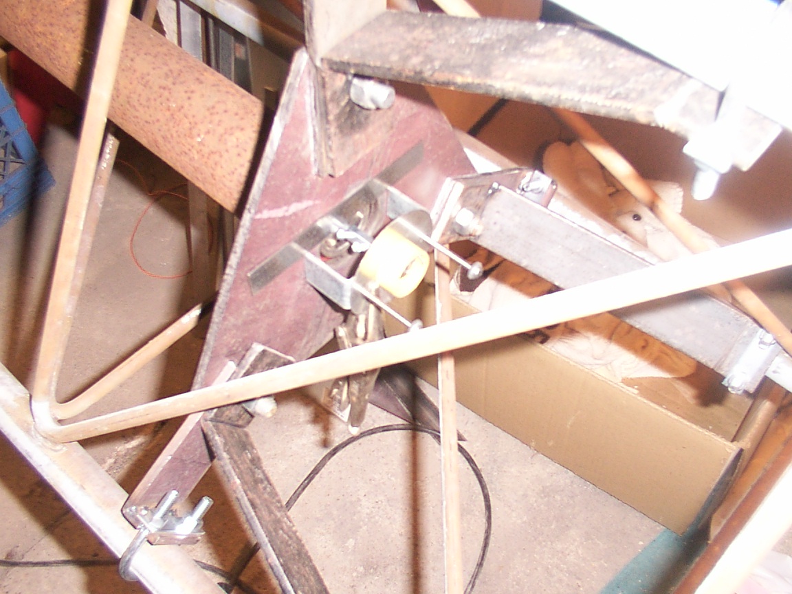
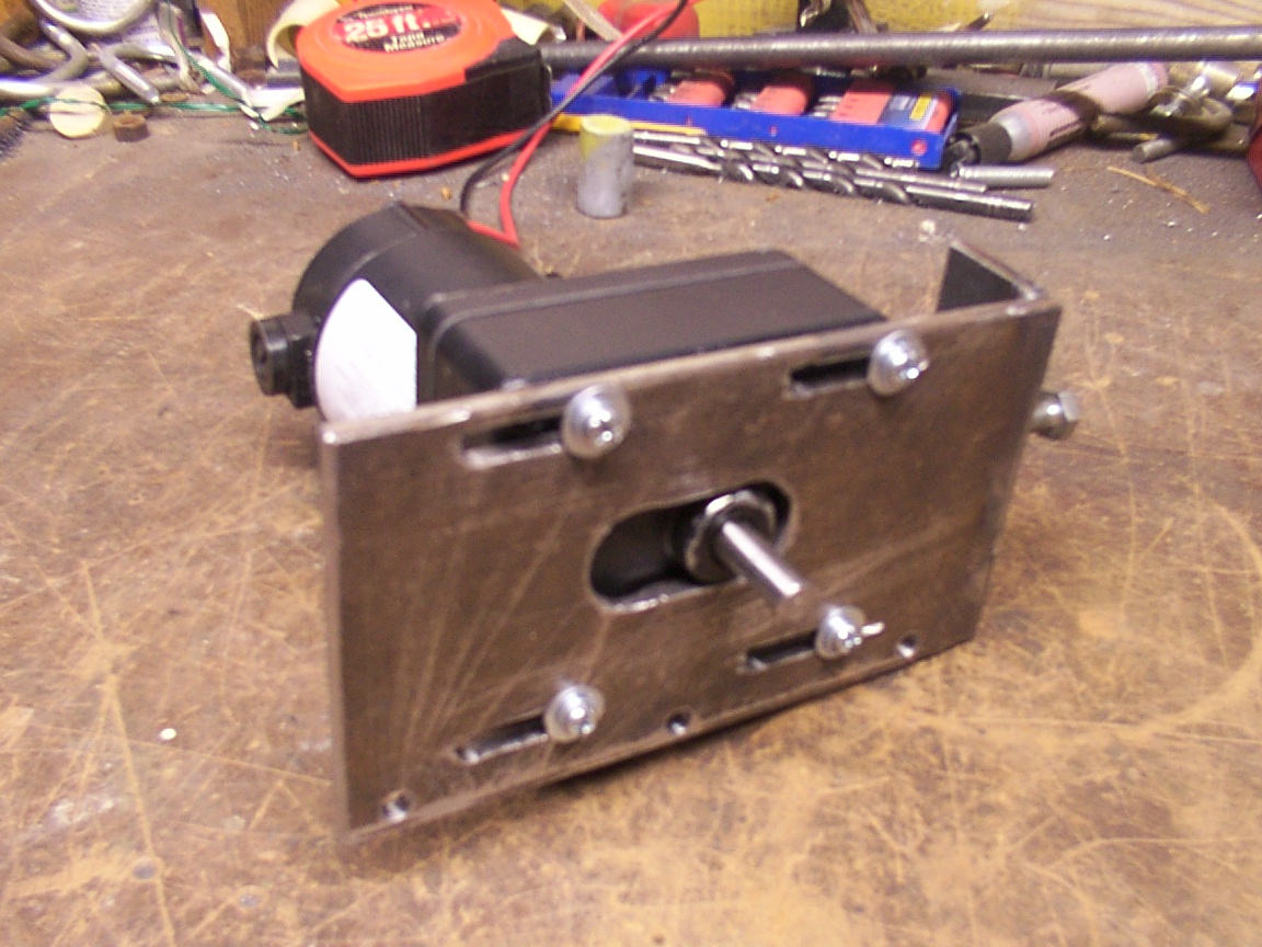
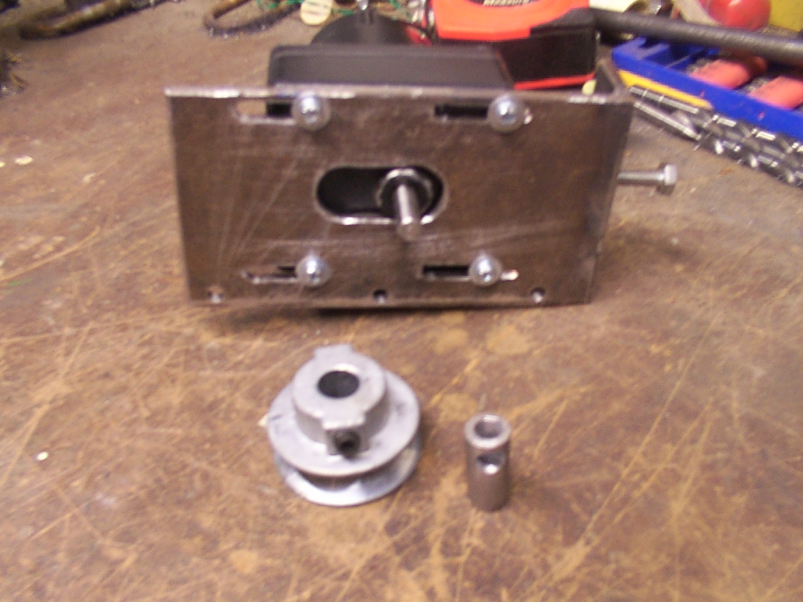
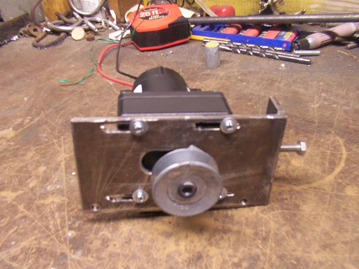
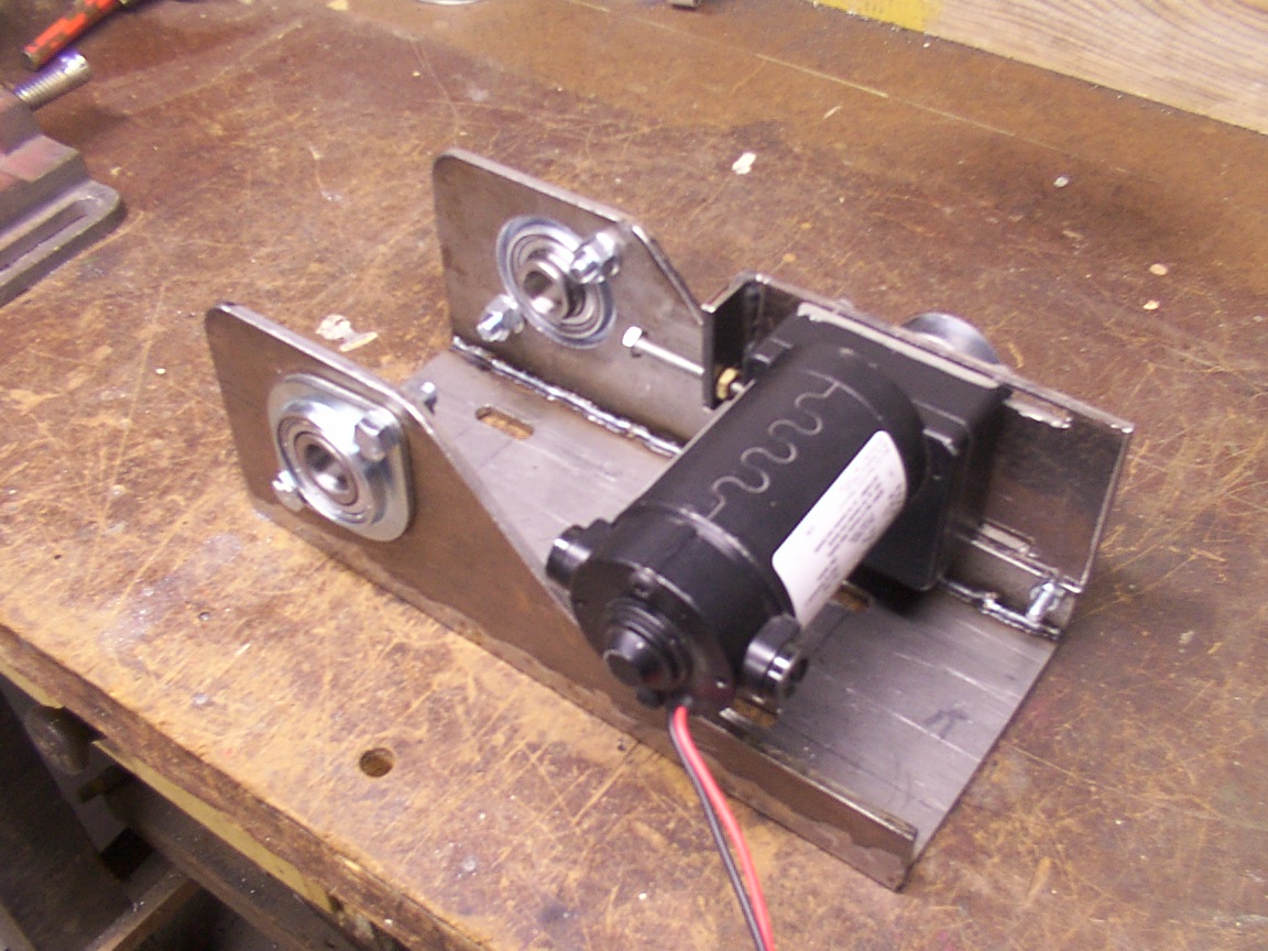
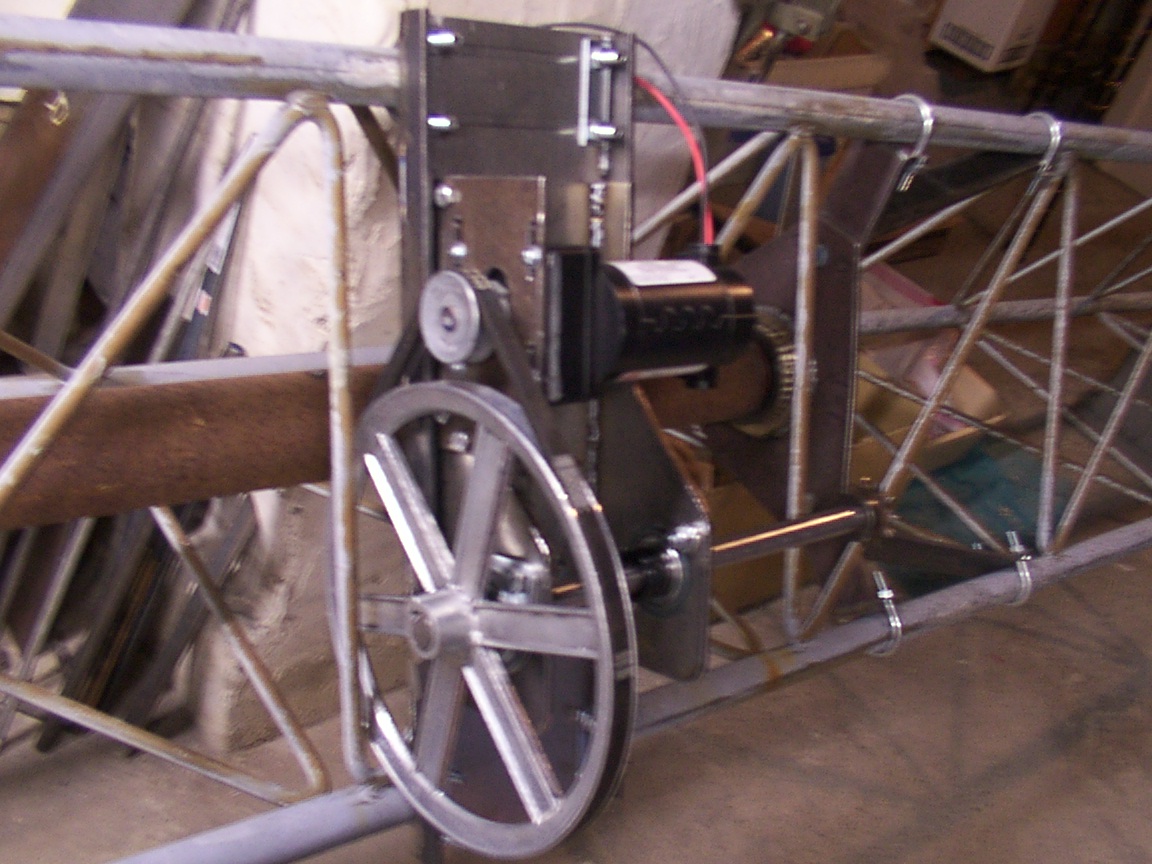
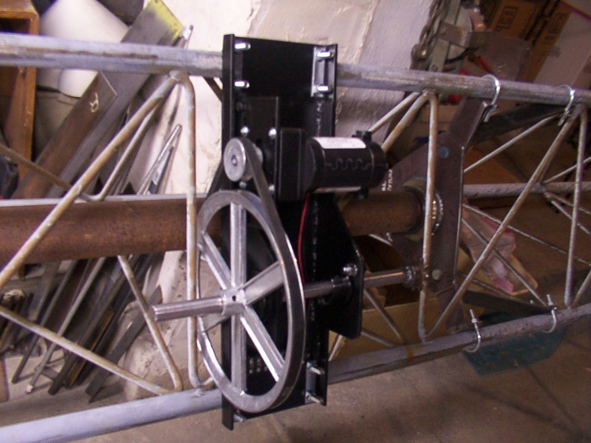
AZ motor & Tention Bracket
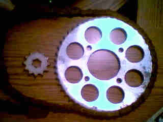
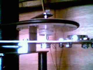
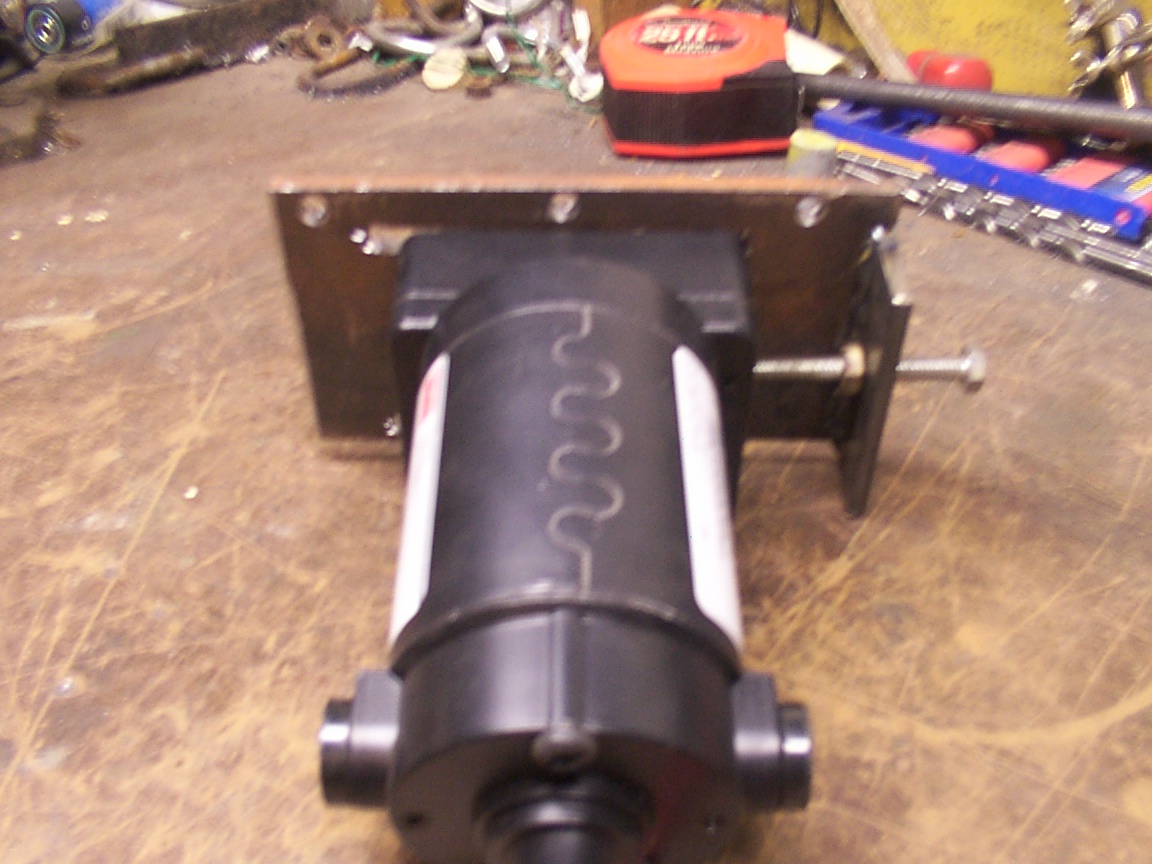
The AZ motor is a Dayton Mod: 1L480, 12VDC 6 RPM gearmotor from Granger. The tention bracket is the first of three brackets for this assembly. The next is the "V" drive shaft bracket. It holds the bearings and shaft, top V belt to motor pully, bottom 12 tooth sproket and the motor tention assembly.
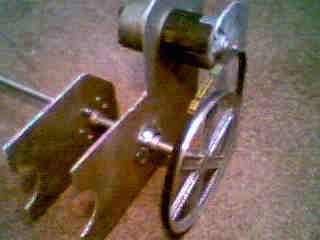
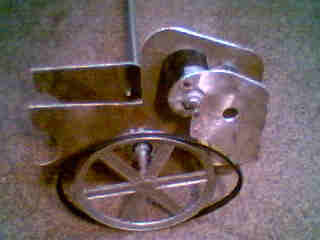
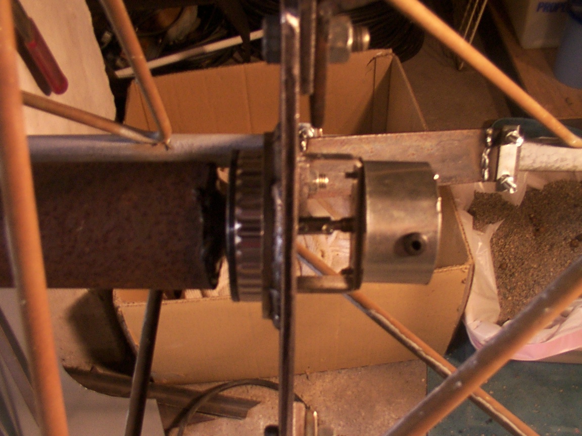
"V" Drive Shaft Bracket
This bracket is made from 3/16ths steel in three pieces. Layed out and cut with a recipicating saw and formed with an angle grinder, I have prints available on request. The assembly "can" be made from smaller flat stock, but must be welded together to form the wider pieces. I choose to purches my steel from a local distrubitor in the sizes I needed. The three pieces of 3/16ths thick 4", 5" and 6" stock enough for "2" complete motor assemblies cost $103.95, but is subject to current market prices.
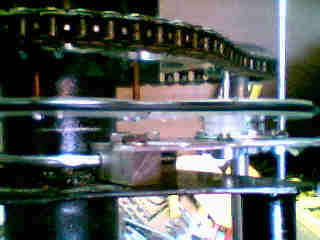
The V-belt pullies I bought at a local Ace Hardware along with the V-belt #4L340, 1/2" x 34". The bearings and flangettes I purchesed at (TSC) Tractor Supply Company along with the sprockets, one 11 tooth and one 48 tooth. The bearings #SA204-12 come with collars. The flangette number is 47MSTZP-2, but others can be used for this aplication.
I totaly boggle the minds of any hardware store employee when they try to help me find what I need as I never know until I find it...So my local store doesn't ask any more, but they do follow me around to see what I find.
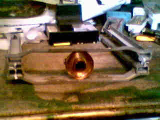
Nut's & Bolts of It
Cutting off the three male ends of the tower and inserting them into the opposit end lining up the bolt holes and leaving about 1" of tube extending out from the female end. Then fitting 1" "C" channel between the three posts which tied the three together. Then cutting three plates of 1/4" x 3", welded over the channel to form the triangle deck. To further center the 3" thick wall pipe AZ drive shaft, three 1" angle iron was welded between the points on the under side closing the space on three points to just at 3". Adding three 1/4"x 1" pieces on top to hold the 3, 1/2" bolts and ball bearings for final support of the drive shaft. The three support bearings are pressed over the three 1/2" x 1 1/4" bolts with a flat washer on both sides of the bearing and a locking nut. The bearings spaced just touching the shaft.
As seen in picture (2), I cut six 1/2" x 12" rods and welded them evenly spaced around the drive pipe as it is smaller than needed to fit the EL assembly. I cound not find the right dia pipe and again my dad had pleanty of 3" thick wall behind the barn. With a little grinding, it fit like a glove. I have two 1/2" tightening bolts and can add two more if its not stable, but don't see a problem yet. So far I have only had to farm out two jobs that I could not do here at home. First being the drive shaft end which my other half had several favors due, so the cost was "zip". Second was the 2 1/4" hole in the lower plate. This being 1/4" thick I didn't have any other way to cut it so I had it laser cut at a cost of $50. Only had to go one block north of the house to get it done. The drive bearing is held in place by a piece of 3/8" square stock bent into a circle using the drive pipe as a form, then tack welding it and forming it as I welded it to the plate. I need to mention that I do not have large tools or machines, I only use hand tools common to most "do it your selfers", other than the small mig welder, a tourch would be nice but I don't have one. The lower support arms are made of 1/4"x2" and to bend the tabbs I had to cut part way through then weld the cuts. The lower drive assembly is "U" bolted to the tower section and I will add a beed of weld under the bolts to keep the assembly from sliding down over time.
Potentiometer Mounts & Covers
The brackets themselves are 3/16" x 1" steel bent to fit and drilled to mount the pots. The pots used are the same as the 8' dish project and are Model 132, Stock # 970-1680, Mfr.'s Type132-0-0-103 Wirewound Single-turn pots from Allied Electronics, 1-800-433-5700. The covers and backing plates are made of 16 gage sheet metal. After cutting them out I used a beer bottle to form them, "I use what I have, that works".
AZ motor & Tention Bracket
The AZ motor is a Dayton Mod: 1L480, 12VDC 6 RPM gearmotor from Granger. The tention bracket is the first of three brackets for this assembly. The next is the "V" drive shaft bracket. It holds the bearings and shaft, top V belt to motor pully, bottom 12 tooth sproket and the motor tention assembly.
"V" Drive Shaft Bracket
This bracket is made from 3/16ths steel in three pieces. Layed out and cut with a recipicating saw and formed with an angle grinder, I have prints available on request. The assembly "can" be made from smaller flat stock, but must be welded together to form the wider pieces. I choose to purches my steel from a local distrubitor in the sizes I needed. The three pieces of 3/16ths thick 4", 5" and 6" stock enough for "2" complete motor assemblies cost $103.95, but is subject to current market prices.
The V-belt pullies I bought at a local Ace Hardware along with the V-belt #4L340, 1/2" x 34". The bearings and flangettes I purchesed at (TSC) Tractor Supply Company along with the sprockets, one 11 tooth and one 48 tooth. The bearings #SA204-12 come with collars. The flangette number is 47MSTZP-2, but others can be used for this aplication.
I totaly boggle the minds of any hardware store employee when they try to help me find what I need as I never know until I find it...So my local store doesn't ask any more, but they do follow me around to see what I find.
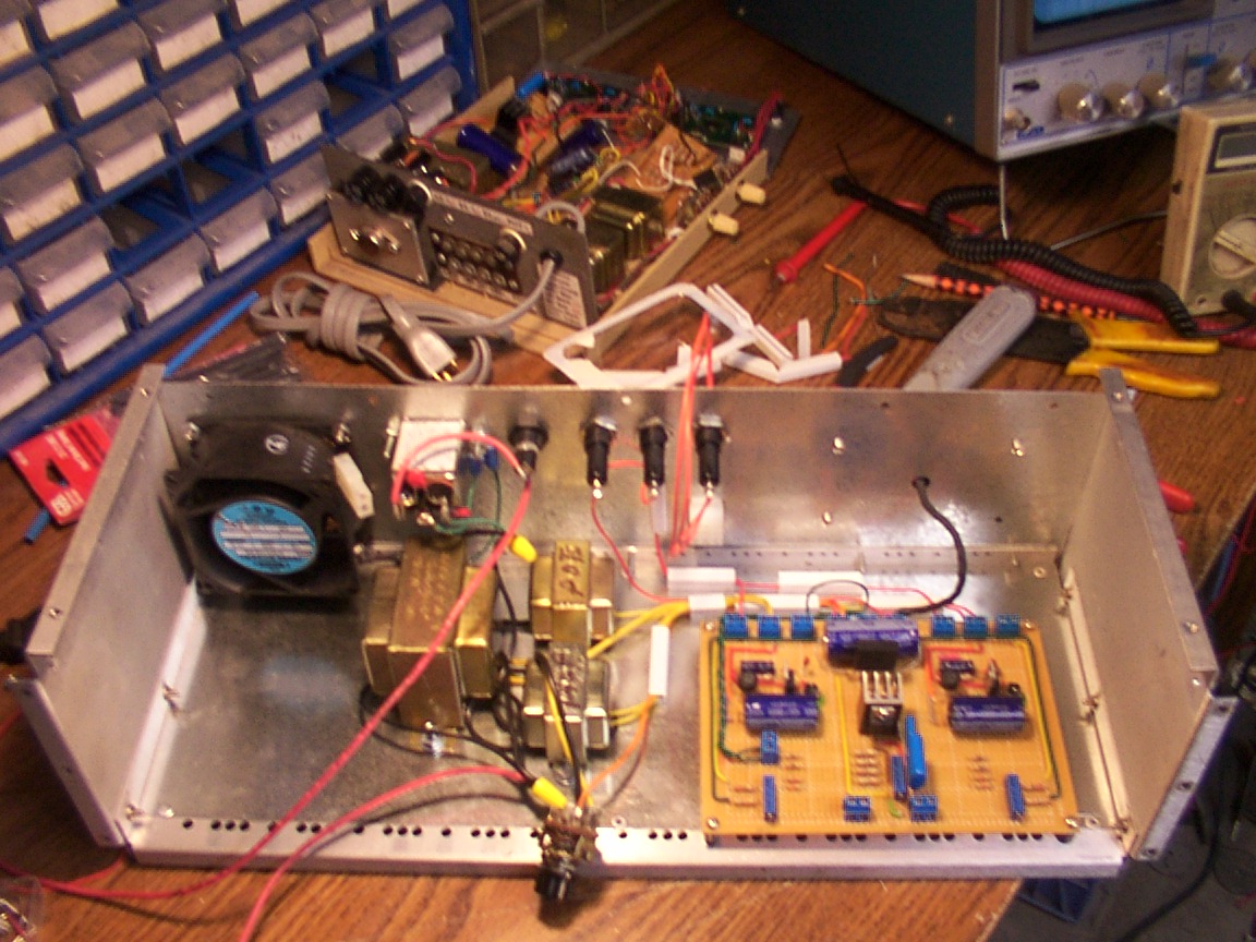
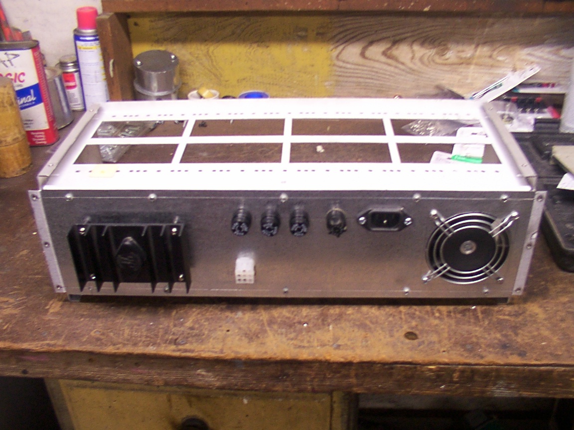
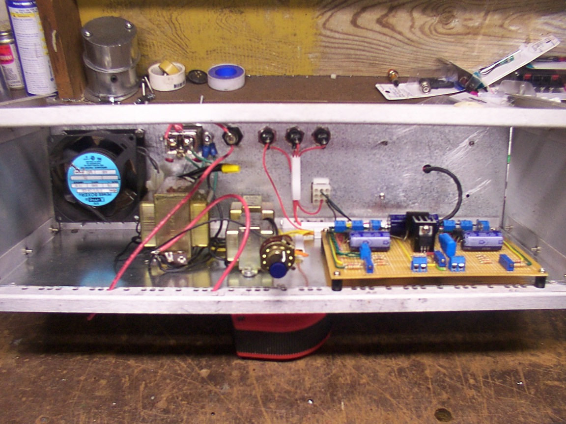
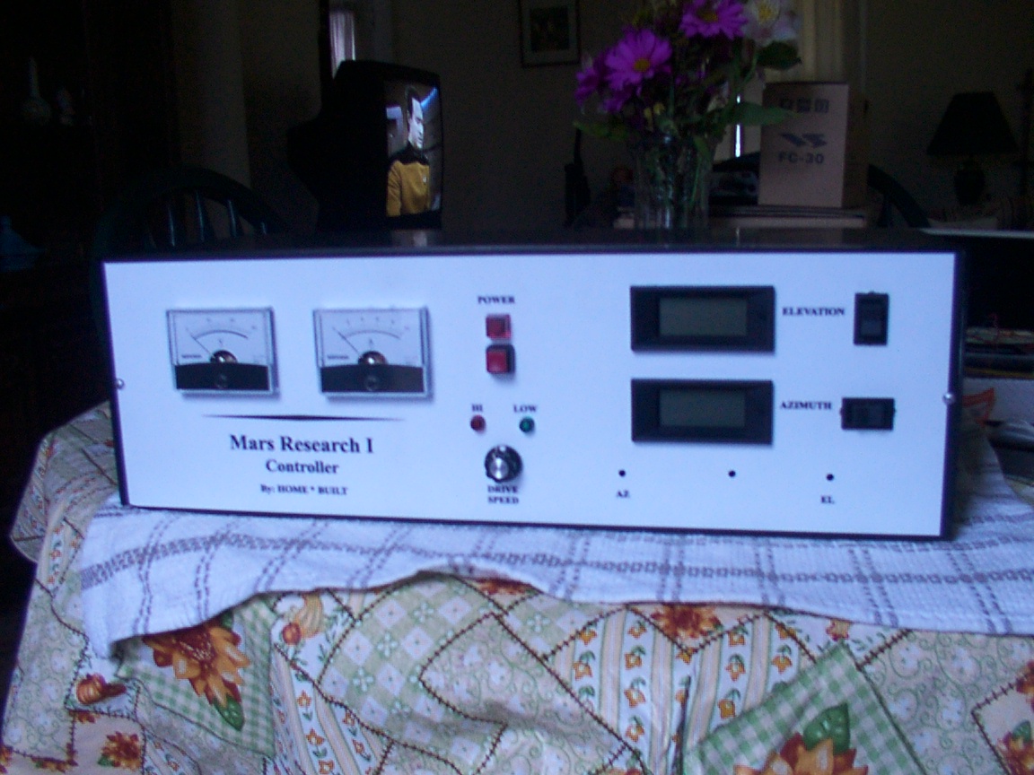
12' Dish Controller
"Mars Research 1"
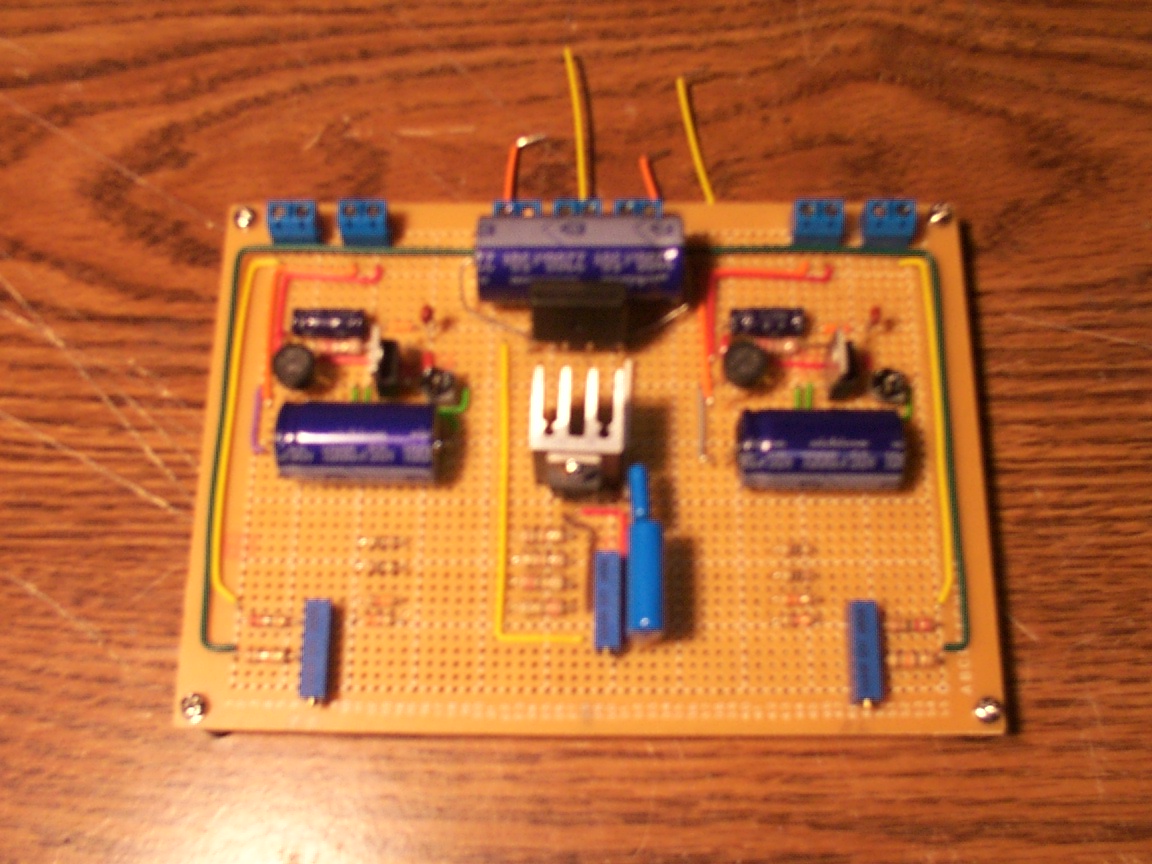
This controller will be the same as my 8' dish controller except that it will have a high and low motor adjustment.
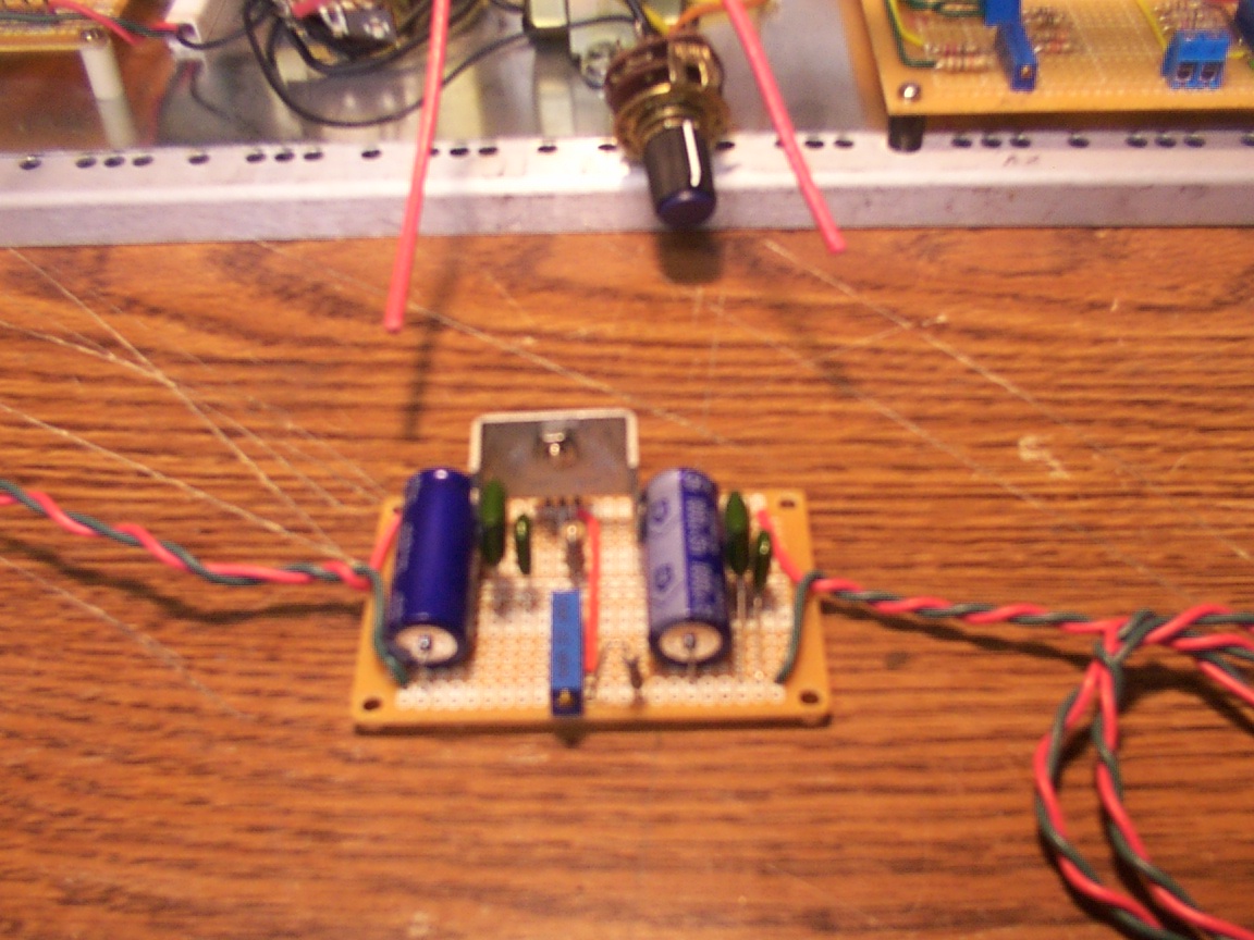
The digital position readout design I started from is Roberts / w0lmd with modifications to the parts I used. The voltage
dividers use a 2.2m ohm and a combination totaling 6620 ohms, this combination best fit the conversison with the pots from
Allied. The pots used are Allied stock # 970-1680, Mfr's# 132-0-0-103. They are 10k continuous wire wound single turn.
Note that they should not have a mechanical stop. The last set of pots I recieved where marked as having no stops but did.
This causes the failure of one pot as it was installed reverse and reached its stop before full travel had been reached. Allied
gets $21.39 each, so you don't want to do this two many times.
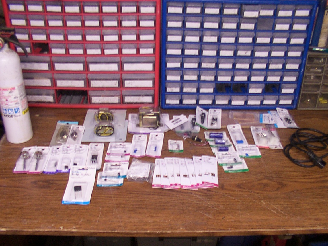
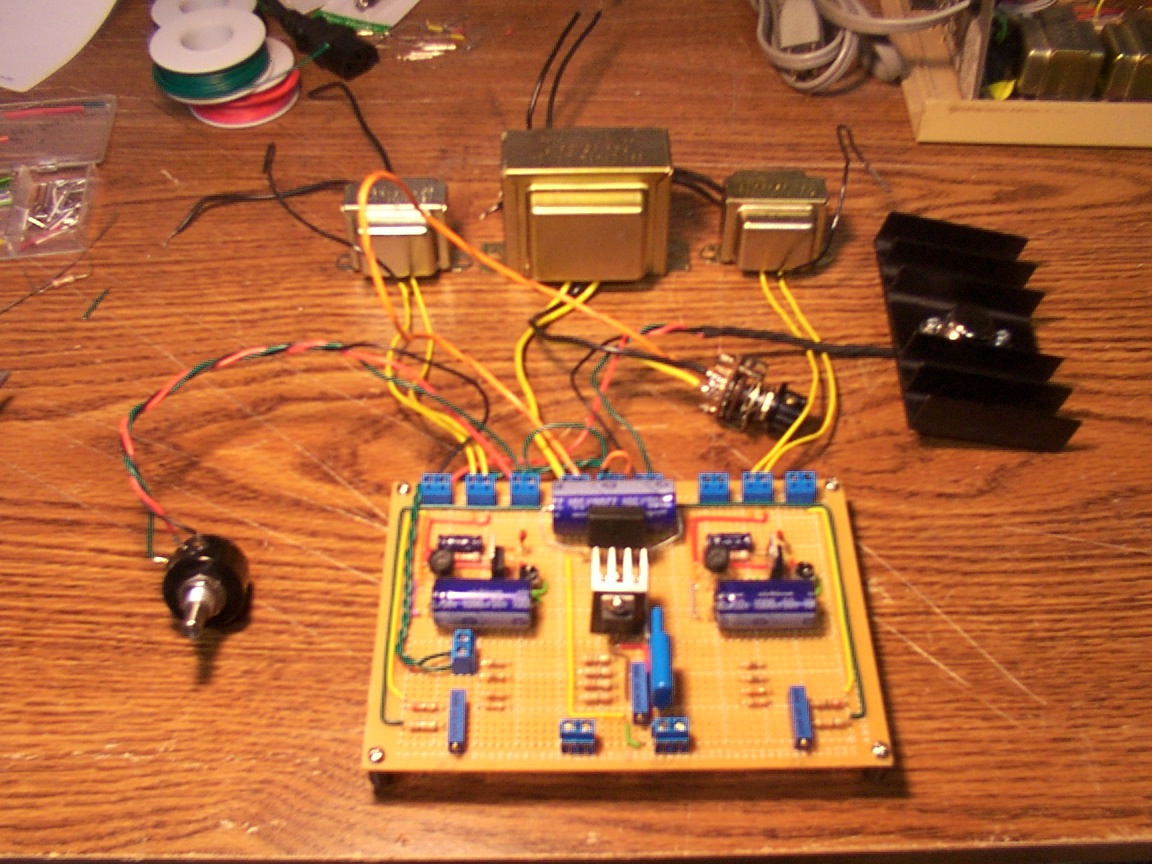
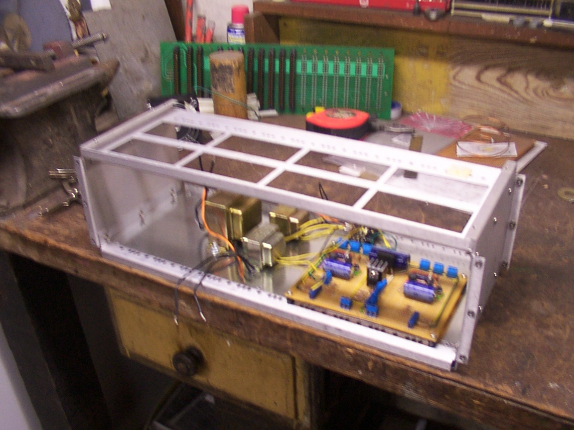
The readouts are Jameco electronics #146835CB and are backlit and cost minus shipping, $19.95 each. Motor switches are DPDT and should be able to hold full amperage of the motors used. This controller will be housed in a standard rack mount and I will later transfer my first controller to the same cabinet as well. I will also add a volt and amp meter to monitor motor condictions, these will be switchable between the two units. All general parts come from Radio Shack including transformers. Anyone needing the 2.2m ohm resistors can get them from me as I purched a large supply of them.
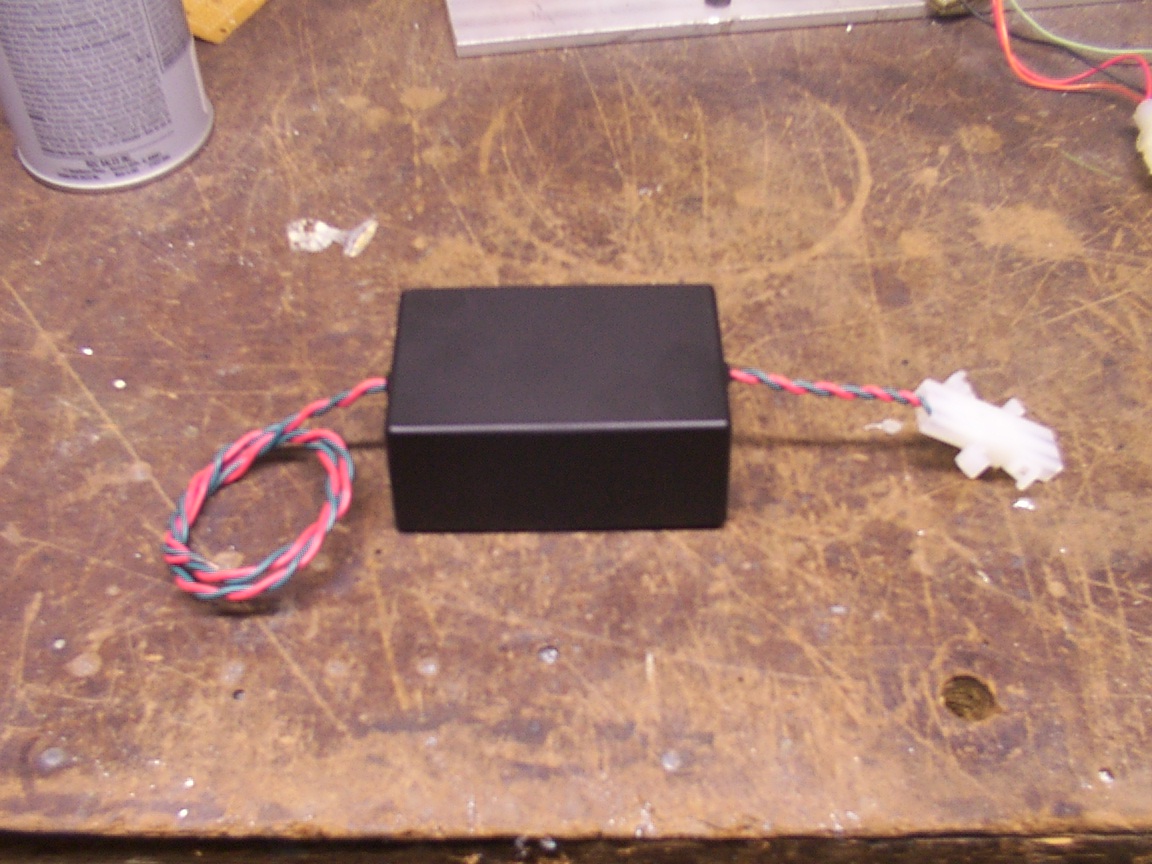
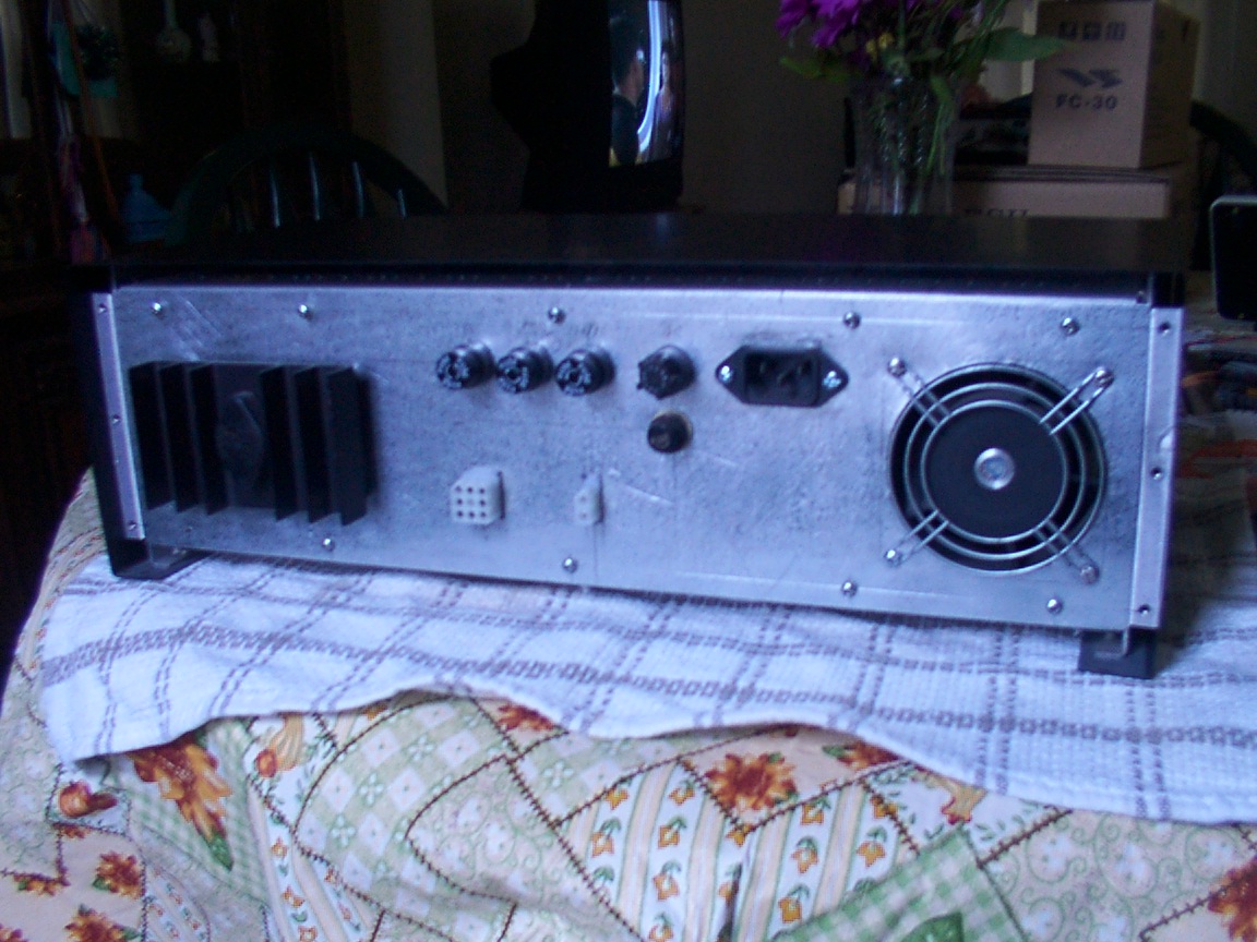
Cabinet being used is from an old battery charge consule a friend gave me some time ago. In the heat sink I placed a 2N3055 as an Amp boost for the motors as the T317 regulator can not handle the heat by itself. I'm also adding a volt and amp meters to monitor both, this being incase of a problem at the dish such as ice or unceen problem that stops the drive movement.
The readouts are Jameco electronics #146835CB and are backlit and cost minus shipping, $19.95 each. Motor switches are DPDT and should be able to hold full amperage of the motors used. This controller will be housed in a standard rack mount and I will later transfer my first controller to the same cabinet as well. I will also add a volt and amp meter to monitor motor condictions, these will be switchable between the two units. All general parts come from Radio Shack including transformers. Anyone needing the 2.2m ohm resistors can get them from me as I purched a large supply of them.
Cabinet being used is from an old battery charge consule a friend gave me some time ago. In the heat sink I placed a 2N3055 as an Amp boost for the motors as the T317 regulator can not handle the heat by itself. I'm also adding a volt and amp meters to monitor both, this being incase of a problem at the dish such as ice or unceen problem that stops the drive movement.
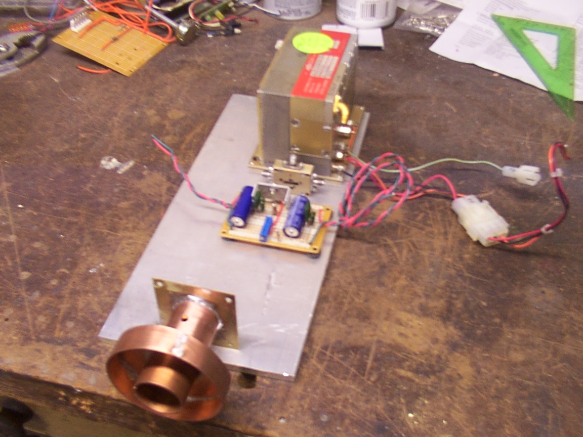
8.4GHz Down Converter