|

Constant Wire Comparisons

Constant Fractal Comparisons

Constant Height Comparisons

Constant Band Comparisons

Wide Band Comparisons
|
 |
Constant Wire Comparisons

(a stylistic note: all graphics in the table below link to full displays)
This is a study of various fractal designs that have one point in common: they all contain identical lengths of
wire to construct a second order fractal. Each of the designs is designated by a first order fractal button at
the left in the table below. On this page there are two wire lengths observed: 64 meters and 16 meters. No particular
care was given to the choice of these dimensions other than their being an order of two. Also, it was a best guess
of physical size to serve MF/HF and VHF/UHF.
This survey reveals that taking a length of wire and applying almost any folding to it will allow
it to retain its spectrum of resonances. By this I mean that it will resonate at intervals roughly matching the
resonances of the monopole it is derived from.
64 Meters
The table that follows contains Reference and Fractal Antennas SWR spectrums for designs consuming
64 meter of wire. It should be noted that due to the manner in which wire is consumed (bent and turned away from
the vertical, or reversed), all fractals are much smaller than 64 meters tall. Observe also that the smaller fractal
antennas produce nearly as many resonances as the large radiator.
The interesting trend displaying separable features is found in three fractals, the Triadic,
M-B Curve, and Z-Fold, showing progressive smoothing of their high Z SWRs in the upper band. The relationships
displayed here are a one-to-one correlation of this trend with complexity.
|
| |
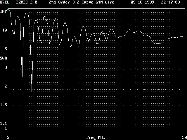
Reference 64 meter tall Radiator SWR |
| |

3-2 Curve 2nd Order 50 Ohm SWR |
 |
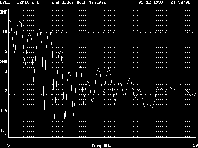
Triadic Koch 2nd Order 200 Ohm SWR |
 |
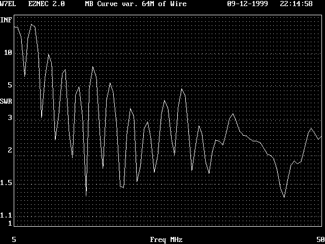
MB Curve 2nd Order 200 Ohm SWR |
 |
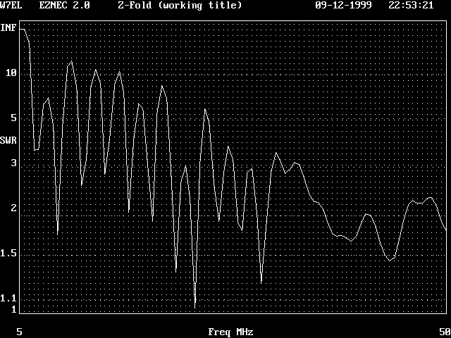
ZFold 2nd Order 200 Ohm SWR |
 |
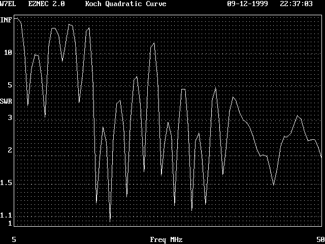
Quadratic Koch 2nd Order 200 Ohm SWR |
16 Meters
In the following table I have many of the antenna designs above scaled to 16 meters of wire.
As always, the first entry is a reference: the 16 meter tall monpole driven against a perfect ground. The remaining
entries all consume 16 meters of wire in tracing the fractal shape also driving against a perfect ground. The net
result is that each fractal is significantly lower than the standard monopole. The table entries are at SWR minima,
a 50 Ohm match is not rare, but by-and-large some minor matching will be required.
The table columns described as x , x element length, H and ordering factor all relate to the
physical dimension. x is the number of unit length elements in the first order form. For the monopole it is simply
one unit length (the unit being 16 meters). H as you may guess is height to the top of the vertical antenna. You
may also note that some fractals have the same x but not the same H. In order to separate out the various designs,
the application of H times element length yields my ordering factor.
indicated value is in terms of (resonant frequency in MHz) * (resonant length in Meters)
to find the length of wire in Meters required for resonance, take indicated value and divide by that resonant
frequency in MHz
| Second Order |
x
|
x element length
|
H |
ordering factor
|
160M
1-2 |
80M
2-4 |
40M
4-8 |
30M
8-12 |
20M
12-16 |
17M
16-20 |
15M
20-24 |
12M
24-28 |
10M
28-32 |
32-36 |
36-40 |
40-44 |
44-50 |
| 16 meter Standard |
1
|
1.00
|
16 |
16
|
|
|
72.96 |
|
222.4 |
|
371.2 |
|
|
521.6 |
|
671.9 |
|
| Sierpinski |
2
|
0.50
|
8.5 |
4.25
|
|
|
78.40 |
|
232.0 |
|
|
390.4 |
|
537.6 |
|
688.0 |
|
| 3-2 Curve |
3
|
0.33
|
7.0 |
2.31
|
|
|
87.68 |
|
251.2 |
|
|
404.8 |
|
553.6 |
|
707.2 |
|
| Koch Triadic |
4
|
0.25
|
9.0 |
2.25
|
|
|
86.40 |
|
249.5 |
|
|
407.2 |
|
566.4 |
|
|
718.5 |
| MB Curve |
5
|
0.20
|
5.7 |
1.14
|
|
|
97.60 |
|
|
267.2 |
|
427.2 |
|
|
580.8 |
|
720.0 |
| ZFold |
5
|
0.20
|
4.0 |
0.8
|
|
|
93.60 |
|
|
265.6 |
|
429.6 |
|
|
589.6 |
|
755.2 |
| Koch Quadratic |
8
|
0.125
|
4.0 |
0.5
|
|
|
107.2 |
|
|
286.4 |
|
449.6 |
|
|
622.4 |
|
798.4 |
Under construction
On the basis of the surveys conducted and presented above, the following "special wire equations"
for length of wire consumed in various low SWR antennas have been determined:
First SWR null (0.25 wavelength)
(73 + (1.20 * x) - (0.010 * x2)) / (F0)
Second SWR null (0.75 wavelength)
(220 + (2.35 * x) - (0.020 * x2)) / (F0)
Third SWR null (1.25 wavelength)
(371 + (3.10 * x) - (0.030 * x2)) / (F0)
Fourth SWR null (1.75 wavelength)
(520 + (3.30 * x) - (0.025 * x2)) / (F0)
Fifth SWR null (2.25 wavelength)
(670 + (3.30 * x) - (0.015 * x2)) / (F0)
The variable x in all equations is for the number of sections in the structure (corresponding
to wires in EZNEC and not segments). These solutions are the best fit to the data provided above and are not suitable
for fractal comparisons where the number of elements in any fractal exceeds 50.
![]()


