Homebrew W7QQQ One Tube Transmitter
On January 22, 2018 I heard a very beautiful CW tone CQing SKCC on 40M. It sounded like a locomotive whistle. It was Jack Meadows W7QQQ and I made contact. After the QSO and viewing his primary transmitter on QRZ.com, I sent Jack an email to complement him on his beautiful sounding transmitter and construction. The schematic for Jack's transmitter is depicted below:

At the time I was building a 6T9 transmitter for the 2019 ARRL SKN. My goal is to construct the W7QQQ transmitter next. My original plan was to build the transmitter on a board similar to Jack's design and power if from either a Heathkit HP-23 or Drake AC-4. I made a decision not to build the transmitter on a board like Jacks exposed wiring and components) because my grandchildren like to play in the radio room when they come to visit.
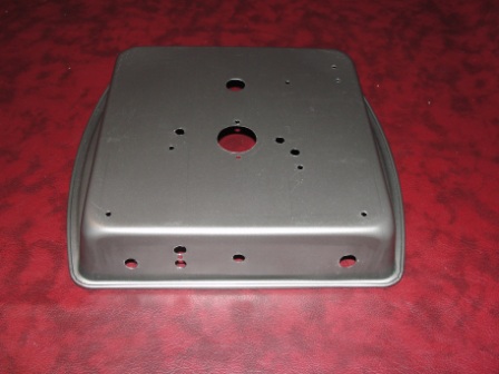
September Update: The autumn temperature in Texas is now tolerable making the garage workshop usable in the mornings. My XYL was throwing out a cake pan, so I decided to use it as the chassis to experience the challenges amateur radio operators did in the past. Here are a few pictures of the project.
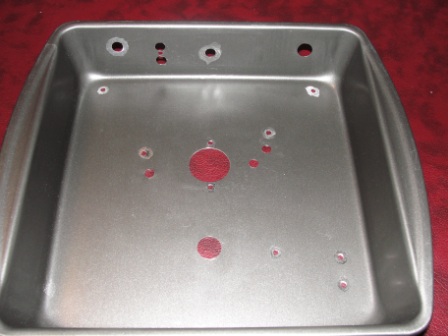
Here are a few pictures of the drilled chassis depicted above. I had to dremel off the cake pan coating around areas that required a connection to ground. Working with thin metal has it's challenges. The best approach when drilling holes is to start with a small bit, and increment up to the hole size you require. A stepper bit maybe a better alternative to drill bits. Also, I had clean up some of the holes after drilling to remove jagged edges.
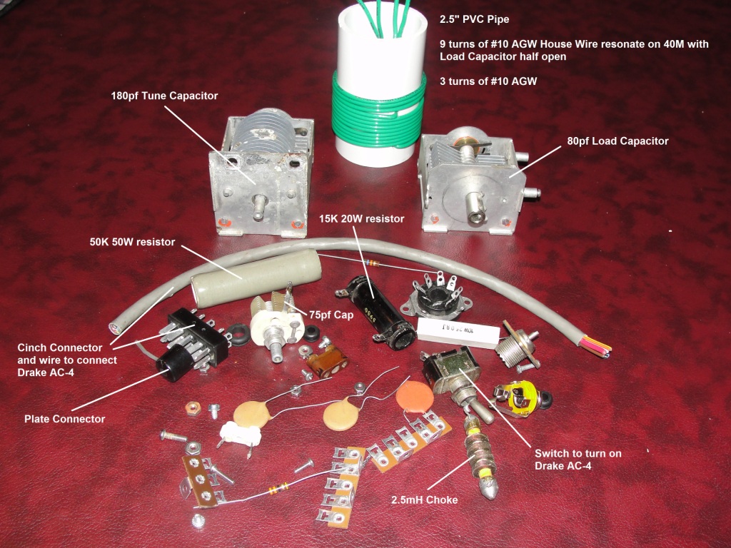
Here are most of the parts from my junk box as depicted above. For the tank coil I used 12 gauge wire I had left over from a homebrew Bravo-7KR antenna project. I validated that the tank coil resonated on 40M with the tuning capacitor half meshed. Also, the large resistor is a 50K 50W resistor and not a 100W resistor recommended by Jack. I did not have a 100W in my junk box, so the plan is to try the 50W and see what happens. Also, I did not have any .01uf 2KV caps in the junk box, but found several .005uf 3KV caps. I will use two .005uF caps in parallel. The variable capacitors are not the exact specifications, but we will give them a go.

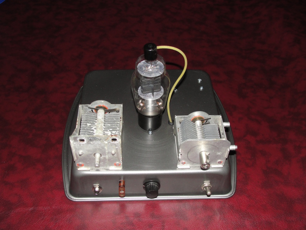
In the picture above, I am beginning to assemble the W7QQQ transmitter. The Tune Capacitor is on the top right, the Load Capacitor is on the top left. When I began this hobby, I remember purchasing these capacitors from a surplus military electronic shop called Rileys. Rileys was located on Industrial Blvd near downtown Dallas and his warehouse paralleled the train tracks. Riley would get a train car load of military surplus equipment, part out the components, and sell them until the train car was empty. I loved going to this shop whenever I could. I also mounted the xtal socket and a 75pf variable capacitor for the xtal section.
October 8 Update
Added RG58 center conductor wire to the tube cap connector, the Tune and Load Capacitors. I also added some of the passive components to the terminal strips and tube socket.
In the picture above I added the 1/4 inch socket for the keyer, and a toggle switch to turn on a Drake AC-4 power supply. While fitting a length of RG58 center conductor with the 6BG6GA tube in the socket, I encountered an issue when removing the plate connector from the tube. The plate connector came loose from the tube's glass.
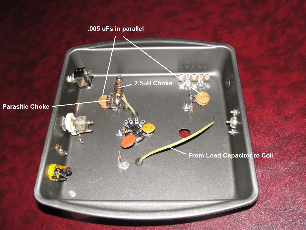
In the picture above, many of the passive components are installed on the tube socket and terminal strips. I also discovered the cinch connector I found in my junk box to attach the Drake AC-4 was not the correct type. The cinch connector I had in my junk box was for a Drake PS7. I found the correct cinch pin on EBay, so I placed an order. As for the two .01uF capacitors depicted in Jack's schematic, you can see the two .005uF capacitors I soldered in parallel.
October 9 Update
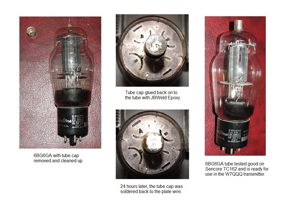
The 6BG6GA tube cap was unsoldered, old glue removed, and plate wire cleaned as depicted in the picture above. After the JBWeld set up over night, the plate cap was soldered to the plate wire.
October 11 Update:
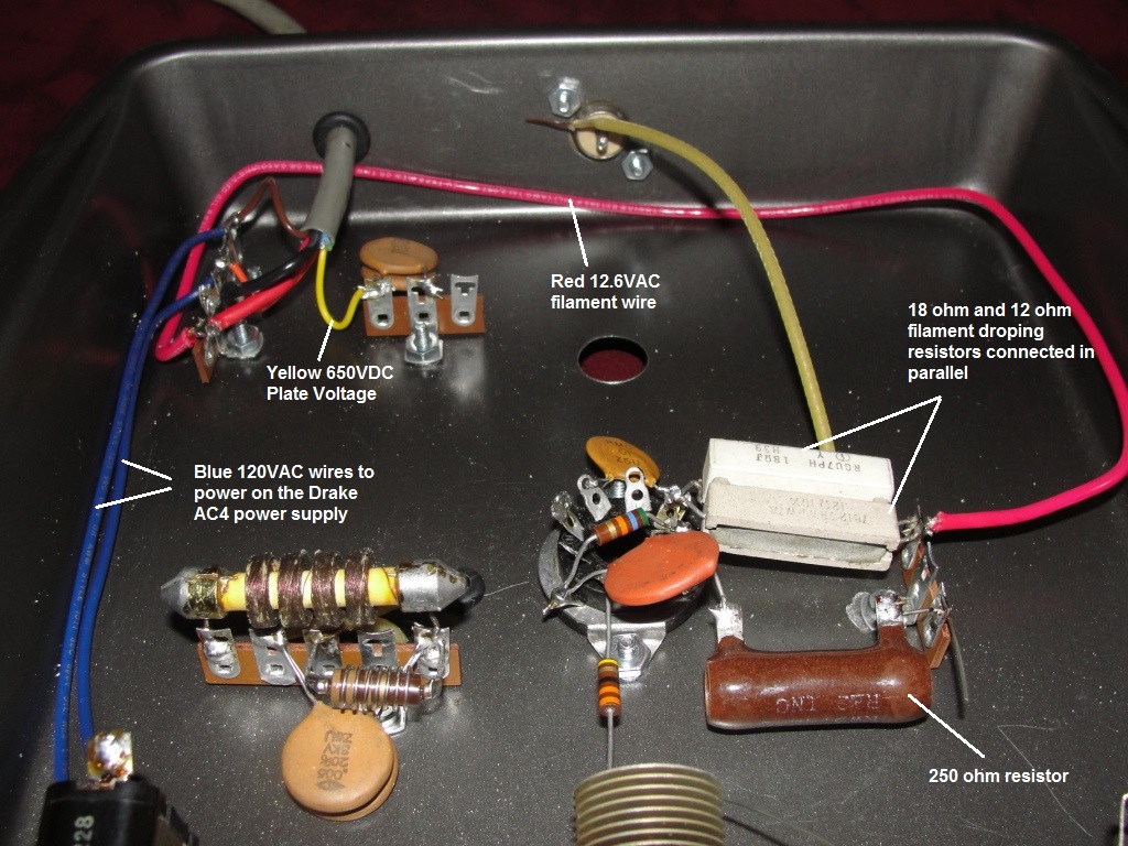
The picture above shows additional components installed. The 250ohm resistor is connected to pin 3 of the tube, and the other side of the resistor will connect to the transmitter meter. I have not determined what junk box meter to use or how to mount it. Also, the junk box wiring harness is attached to two terminal strips and delivers 120VAC, 12.6VAC, and 650VDC from the Drake AC-4 power supply. The return for the 12.6VAC filament and 650VDC is through ground. Sharing the same ground was how Drake designed the AC-4. Given the 6GB6GA tube's filament is rated at 6.3VAC @ 0.9 AMPS, but the Drake AC4 delivers 12.6VAC, it requires a dropping resistor of 7 ohms. In my junk box I could not find a 7 ohm resistor, but did find two 7W resistors I connected in parallel. One resistor is 12 ohms and the other one is 17 ohms.
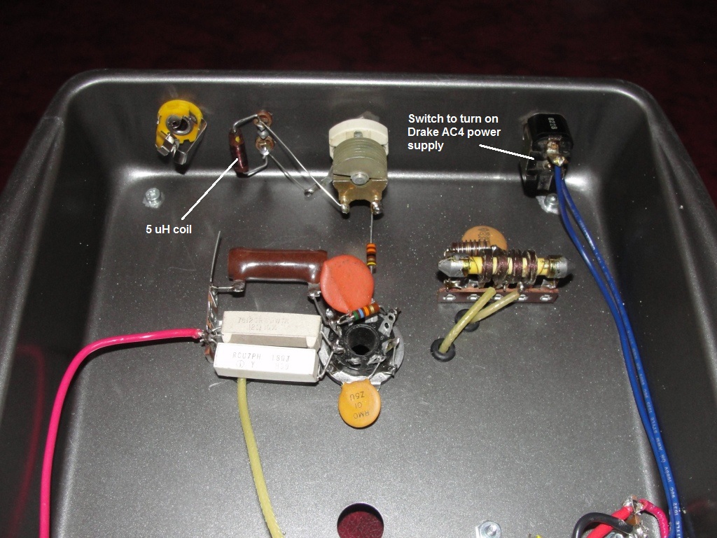
The picture above shows other passive components installed in the crystal section. I could not find a 5uH coil in my junk box, but did find a 6.4uH coil. I was able unsolder/unwrap the coil wire from its lead and removed about 5 turns to move it to 5uH. I had to sand the thin coil wire before soldering it back to its lead. I also connected the two blue wires to the front switch to turn on the Drake AC-4.
October 13 Update:
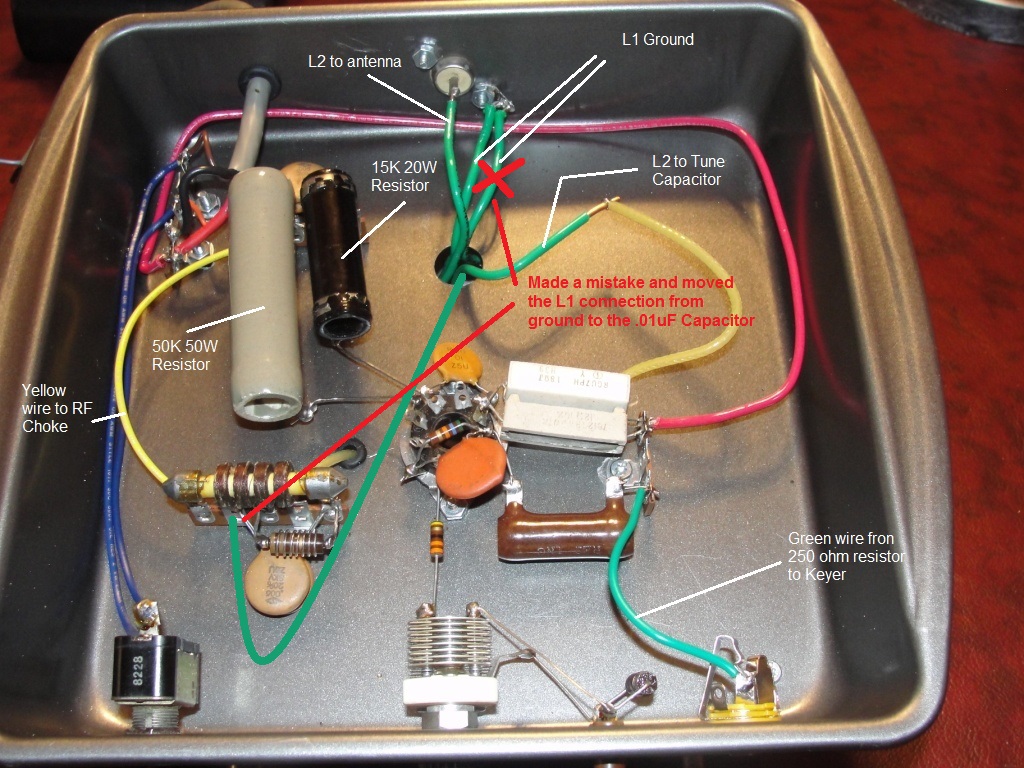
After connecting the 50K 50W and 15K 20W resistors, I decided to temporarily connect everything else up to perform a smoke test. I connected the coil up, and attached the Green wire from the 250 ohm resistor to the keyer socket. During the smoke test, I will attach the meter in series with the keyer. I will be testing the transmitter on a dummy load this evening. Once everything tests good, I will finalize the transmitter and decide how to mount the coil and meter. Stay tuned.
November 10 Update
The W7QQQ will tune up to around 20 watts, but I have to detune the load capacitor to get consistent oscillation startup. Detuning drops the power to around 15 watts with a good CW tone and consistent oscillation startup. Also this weekend I built a three-pole Butterworth pass-band filter for the transmitter. This is to ensure my homebrew transmitters comply with Part 97 of the FCC rules for 43dB harmonic suppression. The pass-band filter is depicted on this website. The following schematic depicts my W7QQQ transmitter version 2:
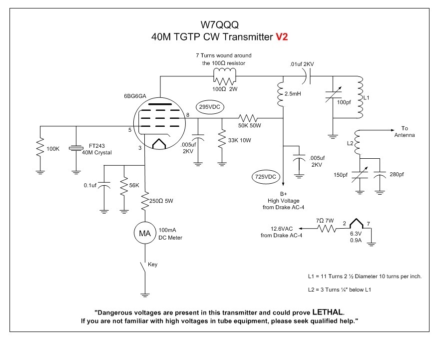
Some of the differences from Jack Meadow's design and the V2 design above are the following:
1. I am using FT243 Crystals. I am still looking for my HC-6 crystals I purchased about a year ago.
2. Replaced the variable capacitor and 5uH coil from the crystal section with a 100K resistor.
3. Changed the 15K 20Watt resistor in the screen voltage divider circuit with a 33K 10Watt resistor. This brought the screen voltage up to 295VDC. On the plate, I am getting 725VDC from the Drake AC-4 power supply.
4. Removed one of the parallel .005uf disc capacitors on the screen, reducing it from .01uf to .005uf.
5. Removed one of the parallel .005uf disc capacitors on the High Voltage input, reducing it from .01uf to .005uf.
6. Replaced the two filament dropping resistors in parallel with a single 7ohm 7Watt resistor I recently purchased.
7. Went with a 1mA Simpson meter.
November 30 Update
As I was searching the ham shack for those HC-6 crystals, I found a 1mA Simpson meter and another 8 pin tube socket. I cannot remember where I got the meter, but its been around for a very long time. I had to calculate the shunt resistor to enable the meter to read 100mA at full scale. I determined the voltage to drive the meter to full scale was 54mV. Using ohms law, I calculated the shunt resistor at .54 ohms. I could not find a .54 ohm resistor in my junk box, but did find a very old .5 ohm resistor. I made a decision to give the .5 ohm resistor a go. The 8 pin tube socked will be used to plug in the tank coil. Also, those HC-6 crystals are still at large.
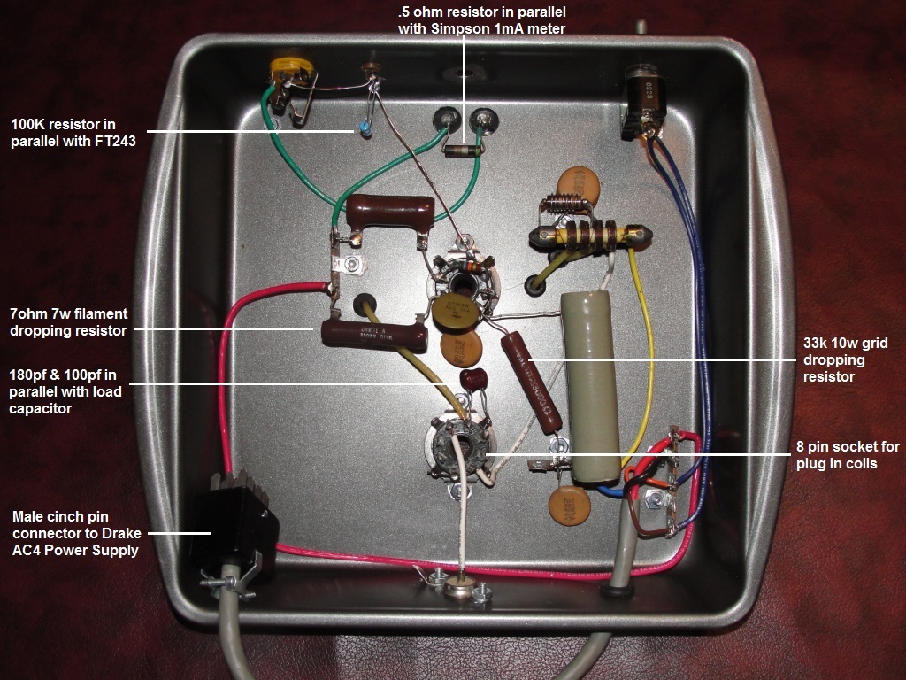
The above picture is what the transmitter looks like from a bottom view. After I adding the 8 pin socket, removing the parallel .005uf capacitors, adding a 7ohm filament dropping resistor, and 33K resistor for the screen voltage network, it really cleaned the clutter.
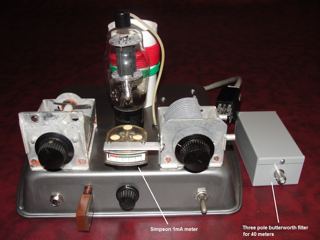
The W7QQQ transmitter is ready for 2020 SKN as depicted above. I had to fabricate the L bracket to mount the Simpson 1mA meter using aluminum strapping material. I also reinstalled the crystal variable capacitor to cover up the hole. In addition, the picture depicts the 3 pole Butterworth filter I will put in series with the antenna when operating my homebrew transmitters. In regards to output, when tuning up the transmitter, it is a little over 20 watts. Unfortunately when you release the key and key again, no oscillation. If you tune up the transmitter and move the load capacitor to slightly more capacitance, the issue with the startup oscillation goes away. Detuning the load capacitor drops the output to around 15 watts. If time allows, I may replace the 100k resistor in parallel with the FT243 crystal with a 2.5 uH rf choke as recommended by Jack Meadows.