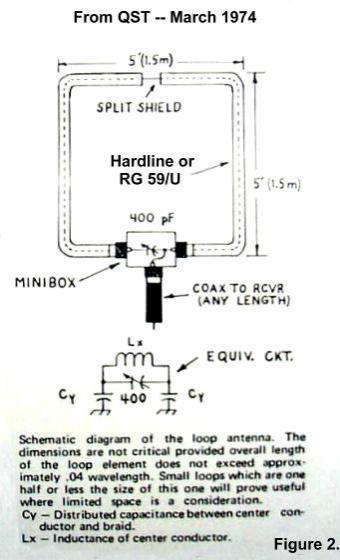
This is an update to the original article which appeared in
QST in March 1974 Pgs. 38-39 (Fig. 2). I made my loop from 1/2"
hardline and used 1-1/2" PVC pipe for the support. Much better
than the old bamboo that was recommended in 1974. The loop can be
made from coax or hardline. It can be in the shape of a square,
diamond or circle. If you use coax, you can place three SO-239
connectors on the aluminum mini-box to ease construction. If you
use hardline, note the method of connecting copper flashing to
the shield of the hardline, and then screwing it with stainless
screws to the mini-box. (Fig. 3 and Fig 6.) Be sure to tin the
areas where the two will be screwed together... the aluminum and
copper do not like each other chemically, and will corrode in a
short time if you don’t tin the areas. A detail of the
connections in the box is in Fig. 4 and Fig. 7.
If you want to make a dual band system, you can do so simply
by placing the two loops on the single support and by using short
jumpers to a tee connector, then you only need one run of coax to
the shack from both loops. (Fig. 5) See the articles available
online by KC2TX at
http://www.qsl.net/kc2tx/
When making the loop, the coax or hard line must have the
outer shield cut away for a 1" length half way around the loop.
This makes the inner portion a shielded loop. Be sure when
cutting the shield at the half way point of the line used, to do
it precisely. DO NOT cut through the insulation. Be sure to
waterproof this area after cutting. The only other component
needed is a 50-400 pF compression trimmer used in series with the
inner loop to resonate the system. Either side of the trimmer can
then be connected to the output connector (SO 239 or similar).
Waterproof all fittings and the mini-box after tuning and
assembly to the desired portion of the band.
Depending on the type of line used for the loop, a
recalculation of the length might be in order due to the
capacitance per foot of the line used. For RG 59/U and the half
inch Hard line, use 10 feet for 80 Meters, and 20 feet for 160
Meters. Refer to the original article or ON4UN’s book on Low Band
DXing.
Since this is a Magnetic Loop, it receives best off the end,
in the plane of the loop. More importantly, it rejects between
30-40 dB end to side. It is better to turn the side to null out
the electrical disturbance you want to reject, i.e. electrical
noise like lightning storms or local QRN on power lines or
neighboring homes. It will still hear most of the RF signals that
get to your QTH. The point is to obtain maximum signal to noise
ratio to hear the weak ones. Since this loop has low output, a 10
dB preamplifier might be needed to boost the signals into your
receiver. I have found that with the Icom 756 PRO, the preamp
will suffice in most cases.
You may note the coil at the base of the loop in Figure 7. I
use this balun to keep any stray RF on the antenna from coming
back down the braid of the lead in. I live near a broadcast
station, and it helps with the local ‘birdies’. It may also keep
my transmitted RF from getting to a preamp. The Balun is made of
15 turns, six inches in diameter of the lead in coax taped
tightly together.
73 and enjoy the Low Bands — Pete N8PR
(SFDXA Meeting May 5,
2004)
To see detailed information go to - SFDXA-
Technical