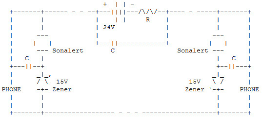
| The application I had was for communications between a high school control room and a backstage location. They had tried FRS radios and UHF professional radios without much success. Markus' design would fit the bill. I just needed come up with a visual indicator instead of an audible one. |
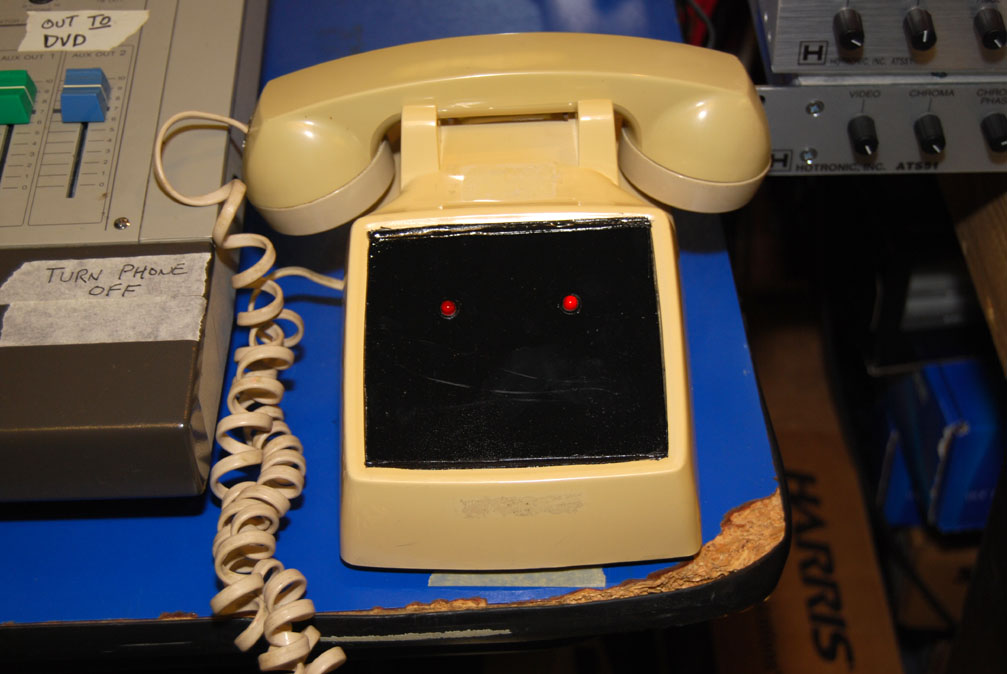
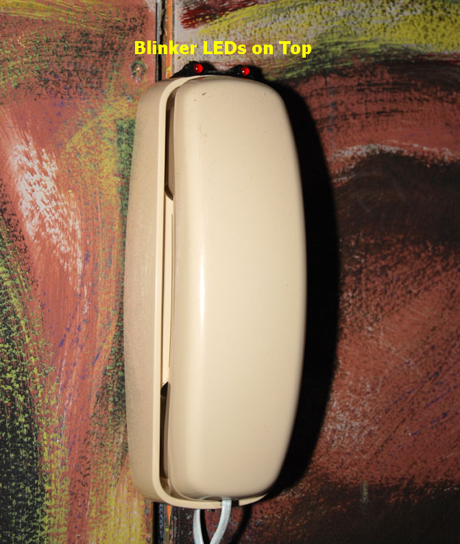
| The circuit that is currently in use has a blinker led and 3.3k drop resistor in place of the Sonalert. The "C" cap is also removed. When one phone is lifted, the built in blinking circuit of the led draws enough current to make a clicking sound in the receiver so the "caller" knows the other phone is blinking. |
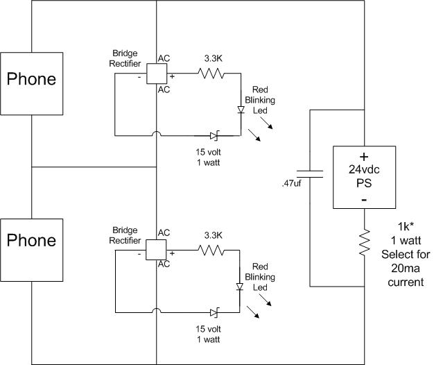
| The circuit is wired INSIDE each phone. This solved one issue and created another. Due to the polarity sensitivity of the 15 volt zener and led, using phones with RJ11jacks can lead you to polarity insanity quickly. Using a small "button" style bridge rectifier solves the "who is positive" wire issue. The blinker schematic is below. The entire circuit can be wired "dead bug style" directly onto the bridge and then heat shrunk. Four wires come out of the heat shrink, two across the phone line and two that lead to the blinking LED. |
|
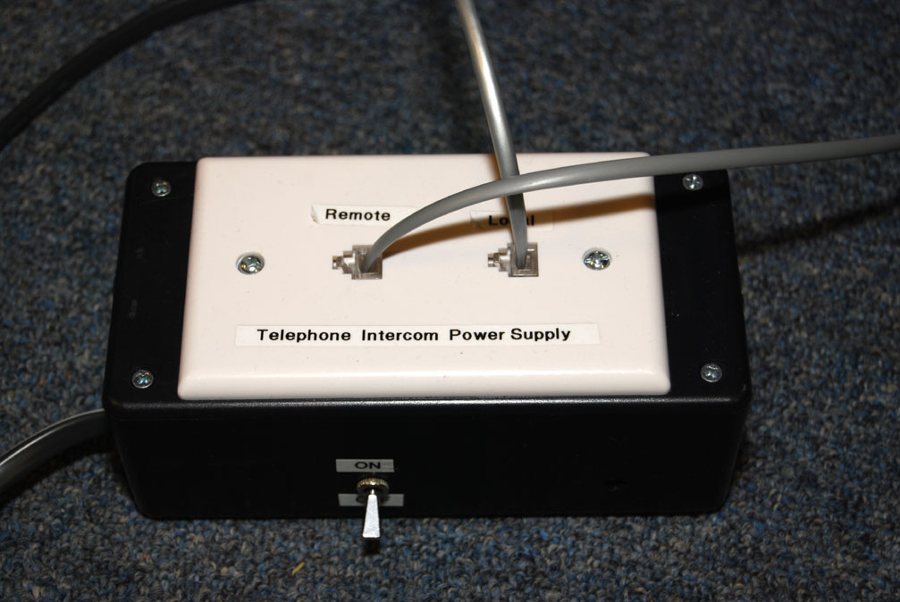
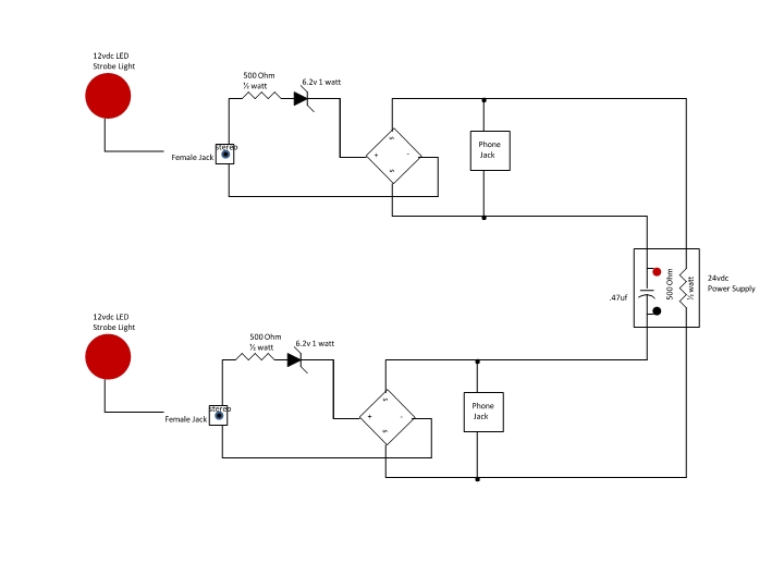
| The blinking LED's are inexpensive and are available from a variety of Ebay vendors. The 24vdc power supply is also an Ebay item. Many vendors offer a completed LM317 regulator circuit board for less than $10 shipped. All you need to do is supply the raw DC. Old HP printer power supplies like model # 0957-2271 for the Office Jet series are great for this. They output 32vdc but any AC or DC supply of greater than 24vdc will work. The supply pictured has a small power transformer that I had in my junk box. The regulator can be built in a Radio Shack plastic enclosure box large enough to have a dual phone jack plate on the cover. The supply is fused at 315ma. (That was the smallest fuse I had at the time of the build)... |
|
|
|
KB2UMJ at yahoo dot com 2013 |
| Update September 2013 |
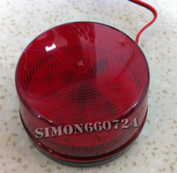
| The small blinkers were a little too small to gain the attention of the cast or crew. So the search was on for something BIGGER. Back to ebay. I found a cheap 3" "flasher" that was LED based and ran on 12vdc. If you search the term "Red LED 12 volt security alarm strobe signal" you will find something that may resemble the picture below.
The bridge rectifier, zenner diode and the dropping resistor are installed inside a surface mount RJ11 (Phone jack). A female 1/8" chassis jack installed through the wall of the jack allows the strobe to strobe to be disconnected if need be. I wish I had taken a picture of the jack before it was installed because it went together very nicely.
|
| |
 |
|
The latest version of the schematic is below.. It is working like a charm. The flasher is MORE than bright enough to get the attention of the teenagers that are running the show. A PDF of the schematic is HERE |
|