RF Chain Construction
|
|
|
|
|
|
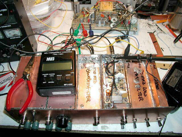
The 1rst LO is now complete, and installed in its enclosure. If you look closely, you'll see that I had to add an extra RCA jack in the rear of the enclosure (I moved the feedthrough capacitor for the supply voltage closer to the floor to make room). This is because I messed up in my original count of "goezinta's" and "comezouta's" by 2. This input is the VCO control from the timing base (it is the voltage that varies between about 2V and 13.5V to sweep the VCO).
I also forgot the VCO sample output which is used by the Tracking Generator. I decided to just run it through an RCA jack in the floor. If you look closely in the front left (lower left in the photo), just in front of the board, you'll see this jack, covered by a protective shielding. Wes, W7ZOI, made careful note that this connector should be well shieled. I took a 1/2" diameter by 1/2" piece of brass tubing, soldered to the floor around the jack, then solded RG-58 shield to it and to the shield of the RG-174 going over to the LO board. It took two tries to get this right. The first time, I melted the center conductor of the RG-174 and shorted it out. The second time, I was more careful and used less heat.