General Practice
My Dipper
MY DIPPER
The project was on an old Handbook and it's
easy to build and efficient;
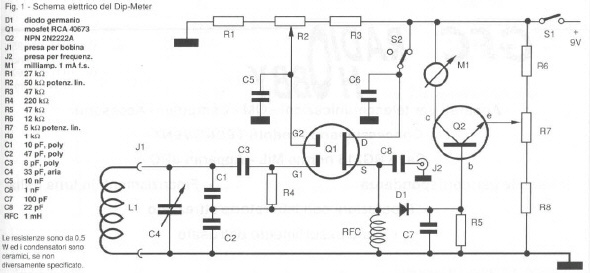
It's a Colpitts oscillator with a variable capacitor and changeable coils; mosfet RCA
40673 (I used a common BF960 or similar) oscillates on a frequency determined by L1 and
C4; oscillation is always stable; R2 sets the gain of Q1 and you need to use it just
sometime; RF signal generated by Q1 is rectified by D1 and amplified by Q2, a common
2N2222A (you can use any NPN transistor); R7 sets the amplification of Q2 (the meter
gain); it's possible to take the RF signal from C8 and send it to an external
frequency-meter (or to use dipper as signal generator). S2 switch dip or wave meter. There
is only a small 9 V battery.
I must say you that I built my dipper on 15
August, when all shop were closed; I needed it to tune my new quad antenna quickly because
19 August I'll go away in army...; so you can see that I built it using disparate
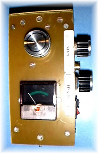
materiales: the box was built using the same stuff of printed board, the meter cames from
an Hi-Fi ecc.: but it works and costs as ...a coffee!
- Variable capacitor need to have a low
minimal-capacitance: if not so, no problem; you'll have a small frequency range and you'll
just need more coils; when you tune the dipper (and your hand is near it) there's a small
frequency-variation; I know that occurs in all dipper; may be you can solve this problem
using long-insulated axle for knob or varicap diode instead of variable capacitor.
- Coils are built on PVC pipe and common TV socket
(it work, but isn't the top); my coils range is 7 to 60 Mhz (and up; my frequency-meter
can't measure frequency higher then 60 MHZ); just one time I needed a coil for 3,8 MHZ but
there was not oscillationes on my dipper: so I simply added a parallel capacitor to the 7
MHZ coil and it worked fine; that means the value of C4 is low for low-band: add a
parallel capacitor on an other coil or add one to C4 and put it in circuit with a switch.
Will be better to use tube socket as coil-support or BNC or PL; do not use audio jack or
RCA.
- Meter cames from an old Hi-Fi.
- On commercial dipper you can read the frequency
on a scale printed on: I think that's not useful at all and is better to use an external
frequency-meter or monitoring the dipper signal with a receiver;
- Using an external frequency-meter there was not
enough signal for reading it; don't change C8 (I tried that, with no success); so I built
a small RF amplifier with a fet: now it's better but sometimes I still can't read it on my
frequency-meter (don't worry, my frequency-meter is a CB one, so it has very low
sensibility.
- Take Q1 gain as low as possible (using R2); if
necessary use R7 for more meter-gain.
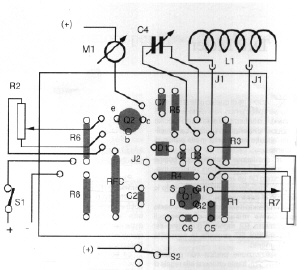
PRINTED
BOARD
COIL DATA
PHOTOS
BIBLIOGRAFY
Radio Rivista 10/92 pag 23
Radio Rivista 4/95 pag 30
Radio Rivista 8/97 pag 27
Radio Rivista 8/94 pag 45
Radio Kit Elettronica 3/89 pag 28
Radio Kit Elettronica 2/88 pag 21
Radio Kit Elettronica 5/89 pag 29
CQ Elettronica 11/89 pag 32
CQ Elettronica 4/89 pag 36
CQ Elettronica 7/97 pag 77
Nuovo Manuale dei Transistor (G.KUHN) pag 265
73
de iz7ath, Talino