Tektronix 475 oscilloscope
|
Back
to the
Emanuele Girlando's Home page
|
|
|
|
|
|
An experience fixing the vertical position pots
|
||
last
update 7/4/2001
This page logs
an attempt to fix a problem on my tek 475 scope. Both the vertical position
potentiometers (pots) were so noisy to make my scope unusable. After failure in
fixing the problem by turning back and forth the pots for the full rotation, I
decided to open the scope to see if it is possible to squirt some kind of
contact cleaner inside the pots.
Opening a
475 is an easy matter: just unscrew a couple of screws at the back panel and
remove all the four stems from the back. Then gently slide the frame out of the
box, paying a lot of attention not to touch any of those fancy components
coming into sight during the manoeuvre.
Surprise:
the to pots are armoured and no chance exists to squirt anything into them.
The only
choice was to remove the pots out of the vertical amplifier board (vboard) to
open them and then attempt a surgery. The operations looked immediately not so
simple. The vboard is full of wires coming back and forth and I suddenly
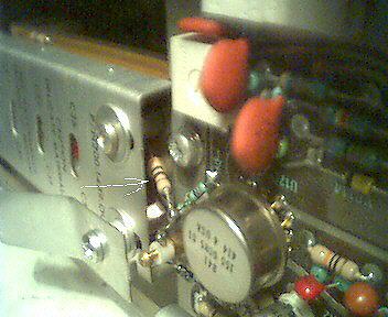
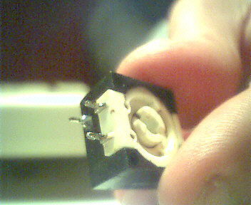
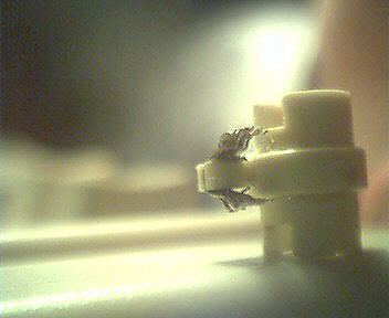
realized that is was also full of mechanical constraints. First of all I
noticed a couple of resistors soldered one lead to vboard and the other to the
vertical rotary switches. Here you can see one of them.
Experience was also suggesting me they were mounted with many critical RF
components electrically connected and physically very close to them.
So I
connected to the Internet and looked for suggestions. No one seems have
described maintenance procedures on our lovely oscilloscopes. But I’ve found
and subscribed a mailing list in groups.yahoo.com titled “tekscopes”.
Here is
what Fred de Vries replied to my message “tek 475 vertical
position pots”
Hi
Emanuele,
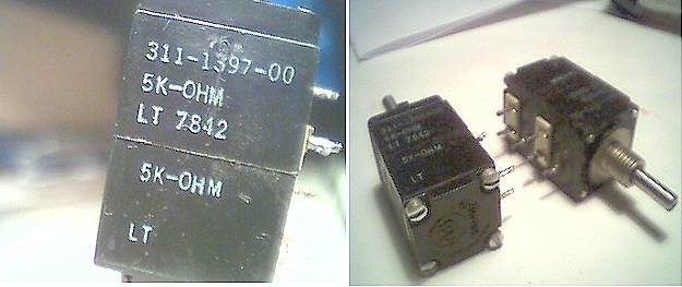
Those
pots are probable Allen Bradly, and have a double section.
There
are two type of AB pots, The plastic sealed ones, and the ones
which
you can nicely open with four screws. To clean the pot, you
have to
take it apart (first remove them carefully from the Vertical
amp
board). Once you have opened them you need to cut the plastic
seal
inside the black plastic section to get to the brown wiper
section.
If you
have everything apart, remove all the old grease and clean all
sections
with alcohol. Mind you that the whiper has a tiny carbon
pallet,
which comes loose very easy.
Once
this is done you need to re-apply new grease. I use for this
purpose
lithium based grease from Dow Corning, Molycote DX. Other
types of
grease I cannot recomend to use. This is probably the same
stuff
that Bourns uses.
After
this, everything has to be assembled again.
There is
one small remark on this whole procedure, that is, if the
carbon
conductive film is worn out, the result will probably
disapoint
you.
I have
personally used this procedure on a lot of AB pots. They are
the ones
usuly having problems due to the aging of the grease. And
can be restored
most of the time with a good result.
- Fred
de Vries
Here is
what Fred de Vries replied to my message “how to safely
dismount the 475 vertical board”
Hi
Emanuele,
input
FET. Just make sure that your soldering iron ground is on the
same
potential as the scope, otherwise you could damage the input FET
(2N5911
discontinued by VISAY). The BW trig view screw (I think allen-
key
1/16") is best taken loos at the switch.
On most
475s there is also a strap from the main board to the
vertical
board which can easy be overlooked. It is close to the HV
section.
You have to unsolder it as well. The same with the Delay
line
which is normally soldered to the vertical amp board.
Good
luck.
Fred de
Vries
For a
complete list of messages go to groups.yahoo.com.
I want once
again to thank you a lot all the participants to the discussion and who
provided so many invaluable tips.
I then
decided to proceed.
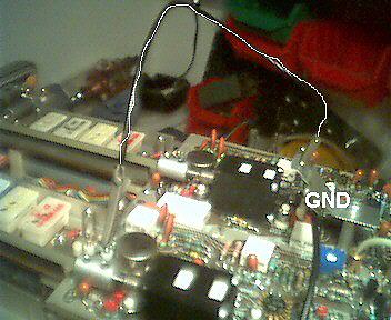
First of
all I unsoldered the resistors. Here you can see the
frame just before the operation; please note the wire (manually lime
lighted in the pic) connecting the lead on the vboard to GND to protect the
input FET . I also measured 18 VOLTS AC between my soldering gun and the scope
chassis, so I also connected the gun to GND… crossed my fingers and the
resistors were disconnected.
I’ve then
spent two hours in dismounting the vboard and un removing the pots from it.
What a nightmare! First of all the screws on the shafts are not 1/16”. They are
smaller – but bigger of my 3/64”. Sgrunt. I had to adapt one
If any
other people is about to start an adventure like this, please be sure to have a
perfect and efficient unsoldering machine. I spent a lot of time trying to get
rid of the tin that was keeping the pots on the board. My solder sucking tool
was insufficient. I used a thin plaited wire to get the tin out of the PCB
holes by capillarity.
The pots are now in my hands, but I don’t really know if
my scope will work again…
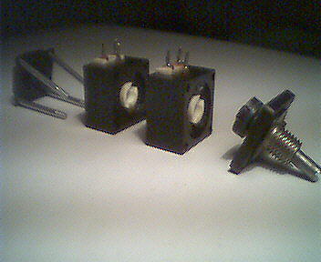
By
examining the pots, I easily figured out that, to dismount the frame, I needed to unscrew the four screws keeping
them assembled.
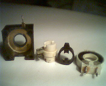
Doing so I
have got the four components of the frame: one shaft support
plate, two pots and a back plate.
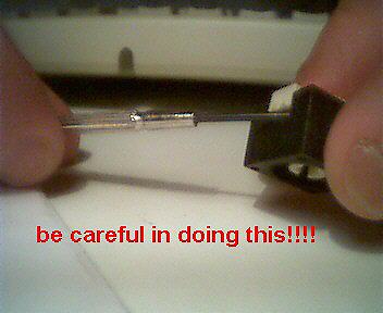
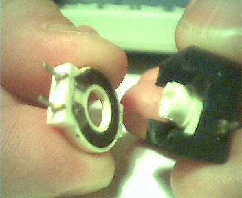
Focusing on
a single section pot, I easily figured out that to
open it I have to get the black and white parts separated. Easy to say, much
more difficult to do. The two part are tightly coupled and even levering with a
small precision screwdriver (1,2mm)
resulted in a failure.
CAUTION:
this is the point where you can destroy your pots!!
Having
spent so many time to get to this point I decided that failure was not an
option. So I insisted. Levering with more force. And more. And more. And… I finally got it open! And these are all the
pieces.
Everything has
been cleaned with isoprophilic alcohol. I wan to spend two words on the wiper.
Be careful. The metallic part of it (the real wiper) is not a single thin plate
of steel as it seems to be: it is a set of steel wires of
hair’s breadth. Do not clean then with Q-tips or you will easily destroy
them of at least you will fill them up with plenty of cotton’s hair you’ll never get rid of.
I made the
clean operation on each section of each pot, remounted everything and … BINGO.
It works perfectly. The pots are now fully and smoothly operational.
While
remounting the scope I have aloso inverted the two trigger pots as the one for
A trigger had the switch unoperative. As trigger B is used much less the
trigger A I have the good switch on the most used trigger. The operation was
trivial.
I don’t
know if what I made on my pots is a definitive surgery. Until you don’t find
any update here, is means that they are still working.
Today is
31/3/2001.
Ciao
Back to Emanuele Girlando's Home page