Back to Emanuele
Girlando's Home page
An experience fixing the
ch1 vertical input of a Tektronix 475 oscilloscope
This page
logs an attempt to fix a problem on my tek 475 scope.
The symptom
applied to ch1 only and was the following:
Applying
the calibrator signal to ch1 with a proven good probe, just rotating the
Volts/div knob, I got the following displays:
|
50 mV/div |
0,1 V/div |
0,2 V/div |
|
|
|
|
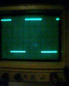

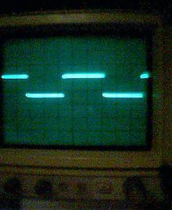
The middle
one is clearly bad. Moving the knob or just moving the scope the shape of the
wave changed sometime to something better, sometime to something worse.
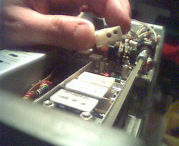
Looking at
the shape I though that the problem should have be related to some capacitor
connected to the input, but only when in the 0,1 Volts/div. As I had the scope
already open because I had just fixed the vpots
problem, I noticed that an array of trim capacitors
is really present for each of the vertical input selection frames. So I turned
on my scope and started to lightly tick the trim caps of the ch1 array. I got
it! Ticking on the first cap of the array (circled in the picture above) I was
able to get the display instable. So I concluded that cap to be the cause of
the problem.
When
thinking on how to get the vertical sensitivity frame dismounted to get the cap out of the PCB, I fortunately
(experience??) tried to pull the cap as if it was inserted instead of soldered.
BINGO! Those caps are not soldered! Their leads are inserted in tiny bushes in
the PCB; think of them like dual-in-line integrated circuit inserted in
sockets. You can remove them just levering with a
small screw driver: be careful, their leads are thinner that hair!
Just
removing the cap, dropping some tiny drops of isoprophilic alcohol, reinserting
the cap, solved the problem.
I don’t
know if what I made is a definitive surgery. Until you don’t find any update
here, is means it is still working. Today is 7/4/2001.
Ciao
Back to Emanuele Girlando's Home page