|
|
Max anodic power dissipation 500 W
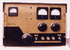
Max anodic tension 4000 V Max anodic current 400 MA Max frequency of use 110 Mhz Feeding of cathode 5 V - 14, 5 V Capacity of entry 7, 4 pF Capacity grid–anode 4, 1 pF Capacity of output 0, 07 pF Typical conditions in amplifier with grid to mass: Anodic tension 3000 V Anodic current 370 Ma Current of grid 115 Ma Anodic load 5000 ohm Power of pilotage 30 W The circuit is classical, but with some constructive personalization dictated by the demand of absolute ghostly purity of answer, in frequency and out effected by tests and instrumental tests. The feeding of the cathode happens from the transformer of filament, positioned in the container of the P. A., through two passing condensers from 1000 pF, and followed by a spool, granted in frequency, in copper tube from 6 mm. what it goes to a foot of the filament, and from a soul in the same in copper thread, of suitable section, isolated in Teflon, that goes to the other head of the filament. For the construction of the spool, a bit is taken of around 50 cms of copper tube from 6 mm., it is inserted him to the inside a bit of thread covered in teflon that suits him comfortable, but not too much, of the length of around 70 cm, and then the everything is wound on a support from 22 (the handle of the broom wood goes well) for a number of 6 coils. The surplus is cut with the special pipes-cut of small dimensions, and to the extreme you are joined, after having rolled up them for a pair of turns, two reofors. Obviously the respective heads are go joined where suitable in the electric scheme. For personal experience, the entry of radio frequency, must be applied, to mean of condenser from 1000 pF, in at all silvered, directly on the footsite of the filament where one of the heads of the spool must be joined in copper tube. In such way we have been able to get 1: 1,1 of R.O.S. of entry, but nothing removes that, if the results were different, experimentally other point of optimal attack can be found on the coils of the spool of accord-feeding filament. Other particularity it is the spool of accord of the p. In fact I have preferred, after innumerable tests, to use a spool to U, that has given the better answer of single dip of accord to us in frequency, and therefore with absolute absence of false dip, thing that instead I have had with the usual spools to coils. I have besides experimented that with suitable and weak cathode polarization (you see trimmer of Bias and negative of return from the – of anodic feeding) we are been able each other to optimize to the best the 3–500Z. In fact amplification surrender the control of Bias, positioned the trimmer to around 22 ohms, it allows the correct absorption of grid (around 120 MA) and of anode (around 470 mA with anodic feeding of 3000 V) The color red-cherry of the anode is the normalcy color of operation of the valve. The suitable anodic line in the scheme is not anything else other than a choke of suppression constituted by a brass strip of 5 mm of width that connects anode - choke of feeding, with a parallel two resistors from 100 ohm / 2W. The constructive characteristics of the choke of anode are pointed out in the table of sketch, and so also the impedances suitable IAF (for the sophisticated the Z–50 OHMITE / value = 7 microH), but they also go well some surpluses to nest of bee from 500 - 600 MA with values of inductance different also). For that mail then on the connector of exit, they also go well values up to 2 mH. With a power of pilotage of around 60 - 70W are pointed out well. Such P.A. you has been the constructive consequence of the P.A. - PT9783. With the pilotage of cathode the power in excess is found again in anode as passing " power ", and therefore the range of power of input for 3–500Z is inclusive between 30 and 100 W. The first variable condenser of the p has to have a low residual capacity that has to wander around the 4 pF max, otherwise it becomes difficult the adaptation of 3–500Z output impedance on the p. The spacing between the armors has to be not less than 4 mm. A surplus condenser, opportunely reduce some plate to get is the necessary spacing, go well, is the value of residual capacity from now on mentioned. The second varying condenser is not critical. The two variable are go commanded to mean sewn together isolated.. The clips of the anodic hood has to be of good quality and with fins to dissipate the heat. For the valves to direct heating, it is not so much main point the tension of feeding, how much instead that of absorption in current, that is opportune to measure it in the case, and it has to be really of 15 A. The fan to snail for the 3–500Z cooling that it happens through the fireplace of the same one (the fireplace is drawn by a jar, type " Bormioli for salse! ", after having does to cut its fund from a glassworker) yoit is commuted in more low speed in receipt not to have disturbed from the noise. The first relay commanded by the P.T.T., pilot the second relay, of power, for the commutation of the polarization of the cathode of 3–500Z and the fan of cooling, other the coaxial antenna commutation's relays. There is besides the command of St. by /Operate, to interrupter, positioned on the frontal panel of the apparatus. To complete the circuit it also departs the tension that goes to command the circuit timer, positioned in the container of the power supply of high Tension, for the start. The electric circuit of feeding of high tension is classic. The transformer is from 1000 VA least, considering that, at the output of the circuit in duplication, it will have to be a tension of , under load, of 3000 V with absorption of around 500 mA max. on modulation. The high tension is transferred to the P.A. unity through coaxial cable and connectors of good quality in the respects of the isolation (the panel connector for the input of the high Tension, place on the back of the P.A., it is male for safety motives) for not to confuse it with that of spar. The container is homemade and following the constructive characteristics: - The frontal panel in aluminum plate of the thickness of 2 mm., of 40 x 27 cm. . - The plan of the amplifier in aluminum plate of the thickness of 2 mm., of 40 x 35 cm. . - The inferior broadside are 5 aluminum longerons, of the thickness of 2 mm., drawn to U of 8cm. of height, of which 2 of the length of cm.40 and 3 of the length of cm.35. These broadsides, two side, a median and the others two, an anterior and a back, go opportunely cut and riveted, or screwed with flared grapevines and dice, in the angles with angular always in aluminum, and such from to form a precise quadrilateral very strong, separated in the frontal sense in 2 compartments. In one the complex of the circuit of the services will come with the transformer of the filaments and that some relays, and in the other the complex of the circuit of the valve with the entry for the forced ventilation. On such quadrilateral it is riveted the aluminum plan previous perforation for the clog of the valve (diameter of 12 cm / inferior diameter slightly to that of the fireplace or of the jar above mentioned) that it will be positioned in the centre of the anterior quadrant side and entry ventilation of the fan to snail (rotunda or square, at the type of fan in possession) that it will be positioned in the back quadrant from the same side of the valve.. - To fix on the panel then frontal previous perforation, the struments (current of grid, current of anode, voltmeter of output R.F.), and the warning lights (H.V., PWR, ST.BY). The perforation for the general interrupter of the P.A., of the interrupter of ST.BY and fuse carriers of feeding and H.V. must be practised after the fixing of the panel, taking them correct measures ( must have perforated the thickness of the frontal panel and the anterior broadside. di I support some panel in contemporary). Behaviour attention to the correct measure for the holes (that they will come with brought buckle, eventually drawn by old potenziometers ) of the must of exit command condenser. - Three fuse carriers , of which, one of high Tension (sets on the negative one / you see scheme in the table of the P. A.) and two of net of the Transformer of the filaments, are set on the frontal panel. - Three fuse carriers, of which, one for the fan to snail and two of net of the transformer of the services, is positioned on the back. - The frontal panel will be strengthened, in the upper part, from broadside at quadrate, opportunely you shape and screwed. - The cover will come subsequently zipped, on the broadside of two angular of aluminum fixed on the side edges of the plan of the P. A. , to mean of grapevines and screws autolock, in way from to be able to capsize it to inspect the inside, and screwed in the anterior part to the same or you hook with special jerky attacks.. - The inferior cover is screwed, with grapevines autothread, around and on the edge of the dividing central to allow a good person estate for the forced ventilation. |

|