ARMY RADIO RECEIVER SET
LAST MODIFIED : October 20th, 2000
AC 14
Receiver. General purpose. Used in combination with many transmitter superceded
many old generation receiver. Manufacturer = Allocchio Bacchini.
Year : 1940
Frequency Range : 75 kHz to 20 MHz in 8 bands
Facilities : CW and RT
Receiver Circuit (Valves) : Superheterodyne. All ECH3. 3 IF channels
65, 230 and 590 kHz.
Aerial : Usually wire or dipole.
Power supply : By PSU type Alim.AC14
AR 5
Receiver. Aviation origin. Part of the ground radio stationA
350/1 and A 300/5
Main difference with original Airforce set is the use of Army valves
type.
Year : 1936
Frequency Range : 21.5 - 1830 m in 6 bands
Facilities : CW and RT
Receiver Circuit (Valves) : RF ampl.(RS22), Detector (RRAF), Pre.AF
(RRBF), AF ampl. (TR2).
Aerial : wire
Power supply : Dry batteries or dynamotor
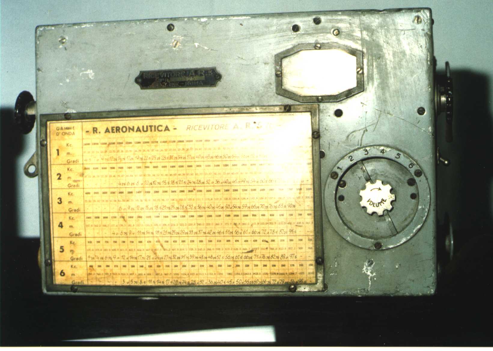
AR 5 Receiver - Tuning knobs (slow and fast) are on the
side of the set.
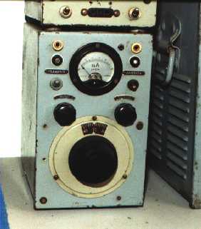
E 433Bs
Receiver. Built in Italy from Siemens under German licence. Part of the
station 10W
UC
Year : 1941
Frequency Range : 27.2 - 33.3 MHz
Facilities : AM
Receiver Circuit (Valves) : Supeheterodyne. 7 tubes all type RV12P4000
Aerial : Whip
Power supply : Dynamotor PSU AK75

E 433Bs Receiver - Italian copy of the German Ukw-Ee.
IF 21S
AC power supply and AF amplifier. Part of theIMCA
0.4 Wstation. Vin 110 to 270 Vca. Vout 6.3 Vdc for filaments and 250
Vdc for TX and RX HT. Inside were also a loudspeaker driven by an AF amplifier.
Valves used : 5Y3 rectifier and EL3 Amplifier.
IF 607
VHF Receiver. Manufacturer IMCARADIO. Part of the stations IMCA
0.4 W and IMCA
20 W
Year : 1940
Frequency Range : 58.5 - 64.5 MHz
Facilities : AM
Receiver Circuit (Valves) :Superheterodyne. RF Ampl.4672, Mix.4672,
Oscil.4671 1IF EF9, 2IF EF9, Det./Preamp.AF 6Q7G. AF output by hearphone.
AF amp. part of PSU.
Aerial : Vertical dipole
Power supply : by ac PSU that include AF amplifier. Can use also dry
batteries with hearphone AF output.
Of this receiver exists also a version with the frequency range modified
to intercept SCR-522 and used mainly in Sicily to monitor Malta communications.
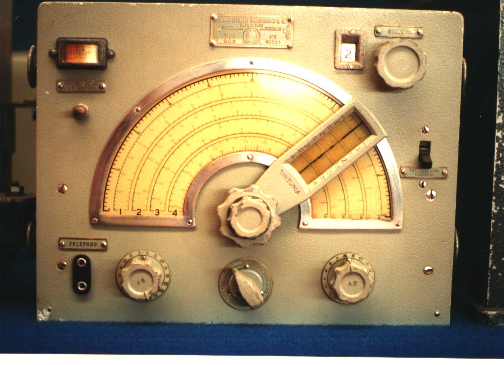
OC 7
SW Receiver. Born for commercial purpose has been used also from armed
forced (Army and Air force)
Year : 1938
Frequency Range : 2,5 - 39 MHz in 5 bands
Facilities : CW and RT
Receiver Circuit (Valves) : Superetherodyne, IF 650 kHz. Valves 78(3),
77 (3), 75, 41.
Aerial : Dipole
Power supply : 110-220 Vca external PSU (OC7C). Batteries 6 Vdc(LT)
and 220 Vdc(HT).
OC 8
SW Receiver. Intercept. Manufacturer Allocchio Bacchini. Part of the radio
station R/200
Year : 1940
Frequency Range : 1,300-20,978 kHz in 4 bands
Facilities : CW and RT
Receiver Circuit (Valves) : Superetherodyne, IF 650 kHz. 6K7G, 6K8G,
6K7G, 6L7G, 6AY8G.
Aerial :
Power supply : External PSU. 6 Vdc or 110 to 220 Vca
OC 8 Receiver - From the OC 8 the Allocchio Bacchini
developped many receivers like the RF4 receiver section and other.
OC 9
SW Receiver. Top performance. Specially used in the listening units to
intercept enemy communications or for General HQ necessity. Manufacturer
Allocchio Bacchini.
Year : 1941
Frequency Range : 2,7 - 30 MHz in 5 bands
Facilities : CW and RT
Receiver Circuit (Valves) : Superetherodyne, IF 650 kHz. Valves = 6K7G
(4), 6K8G, 6L7G, 6Q7G (2), 6C5 (3). 2 RF stages, 3 IF stages and BFO. AF
selectable filter. Sensivity 3-8 microV.
Aerial : Dipole
Power supply : 110-220 Vca with external PSU.
OM 8
MW Receiver. Specially used in the listening units to intercept enemy communications
or for General HQ necessity. Used in combination with SW receiver (OC 9)
to cover 100 kHz to 30 MHz spectrum. Manufacturer Allocchio Bacchini.
Year : 1941
Frequency Range : 100 - 2650 kHz in 5 bands
Facilities : CW and RT
Receiver Circuit (Valves) : Superetherodyne. 6 Valves. Sensivity 4-15
microV.
Aerial : Wire
Power supply : 110-220 Vca or dry batteries
OM 9
MW Receiver. Top performance. Specially used in combination with SW receiver
to cover LW, MW and SW spectrum to intercept enemy communications. Manufacturer
Allocchio Bacchini.
Year : 1941
Frequency Range : 100 - 3000 kHz in 5 bands
Facilities : CW and RT
Receiver Circuit (Valves) : Superetherodyne. 8 Valves (Two RF stages).
Sensivity 5-10 microV.
Aerial : Wire
Power supply : 110-220 Vca or dry batteries
RA 1
Receiver. Portable from one man. Used from infantry, artillery and other
corps for cooperation with airforce. Built in many types with small variations.
The model RA1 Mod.1937 had 4 batteries.
Year : 1933
Frequency Range : ???
Facilities : CW and RT
Receiver Circuit (Valves) : RF ampl.(RSAF), Detector (RRAF), AF Ampl.(2xRRBF).
Aerial : Loop
Power supply : 3 dry batteries
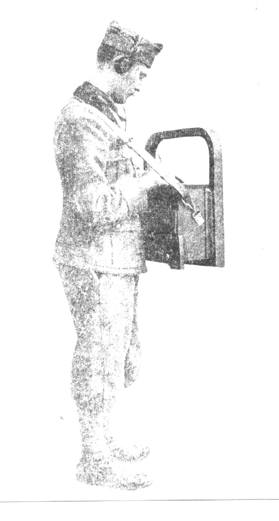
RA 2
Receiver. Used from Signal for cooperation wirh Airforce. Portable. The
complete set were contained in two wooden chests. Carried by motorcycle
or mule.
Year : 1935
Frequency Range : ???
Facilities : CW and RT
Receiver Circuit (Valves) : RF ampl.(RSAF), Detector (RRAF), AF Ampl.(2xRRBF).
Late model with two RF ampl.(2xRSAF)
Aerial : Wire 12 m long.
Power supply : Dry batteries picture
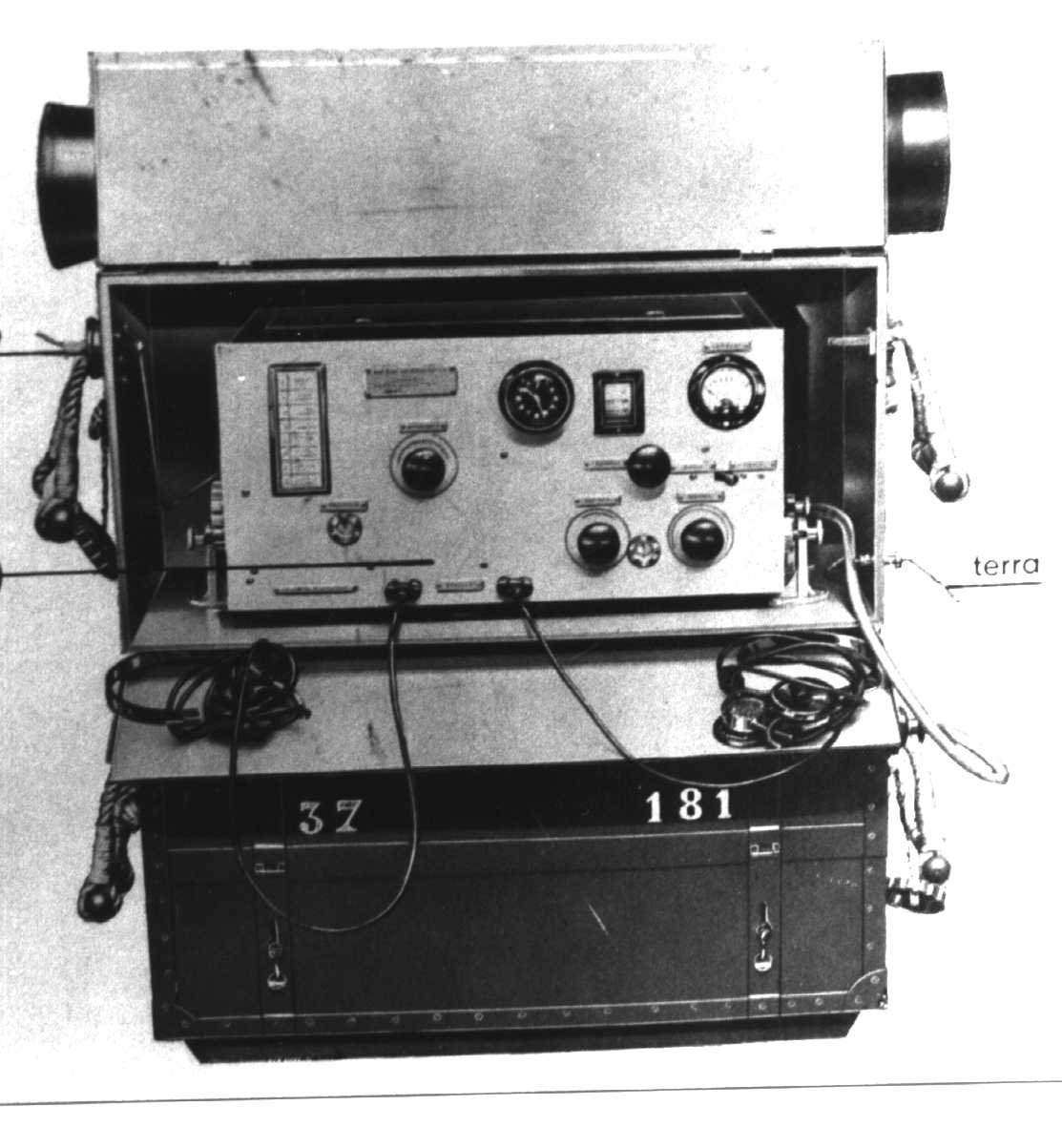
RI 2
Receiver. Intercept and radio net control. Mainly used like field set.
Year : 1935
Frequency Range : 85 kHz to 24 Mhz in 7 bands.
Facilities : CW and RT
Receiver Circuit (Valves) : RF ampl.( 2 x RSAF), Detector (RRAF), AF
Ampl.(RRAF + TR2).
Aerial : 25 m wire
Power supply : Dry batteries suppling 3.6, 9 and 150 V
RI 3
Receiving unit. 3 receiver equipments truck carried. Intercept. SAFAR manufacturer
Year : 1934
Frequency Range : 30 to 100 m in 4 bands and 100 to 3000 m in 4 bands.
Facilities : CW and RT
Receiver Circuit (Valves) : RF ampl.( RSAF), Detector (RRAF), AF Ampl.(RRAF
+ TR1.2). Receiver had two different RF Ampl. and Detector sections (one
for 30-100 m and the second for 100 to 3000 m) with common AF. So the total
number of tubes were 6.
Aerial : 30 m wire
Power supply : 3 systems possibility. Dry batteries, Fe Nk storage
batteries, mains.
Intermediate model used RI2 receiver set and later equipped with AC14
or RR1 receivers.
RR 1
Receiver. General purpose. Manufacturer Magneti Marelli. Replaced many
old generation receivers. Used also from navy and Air force.
Year : 1940
Frequency Range : 1.5 MHz to 30 Mhz in 5 bands.
Facilities : CW and RT
Receiver Circuit (Valves) : 9 tubes superheterodyne (6x 6RV + 2x 6DD
and 1 type 6R.
Aerial : 25 m wire or dipole
Power supply : Separate AC power supply.
RR 6
Receiver. Manufacturer Magneti Marelli. Part of the station RF
3M
Year : 1940
Frequency Range : 1.690 - 1.790 MHz
Presettable frequencies : 4 channels
Facilities : CW and RT
Receiver Circuit (Valves) : Superheterodyne using n. 7 valves 6RV type.
IF = 470 kHz.
Aerial : Vertical
Power supply : Dynamotor PSU supplied to 12 Vdc vehicle battery.
