ARMY RADIO STATION "Non Regolamentari"
LAST MODIFIED : OCTOBER 12th, 1999
A 300/5
Radio station. SW high power ground station. Separate transmitter and receiver
This radio station were of Aviation origin designed for ground controll.
Later modified for army use to allow medium distances communications. Later
replaced by R/200
Year : 1937
Frequency Range : xxx -xxx kHz
Facilities : CW, MCW, RT
Receiver type : AR 5
later model AR 8
Transmitter type: A
300
RF Output : 250 W
Aerials : Transmitter = Long wire with adjustable lenght, 12 m vertical
Receiver = 14 m vertical
Power supply : Engine driven generator (TX) plus 12 V storage battery
for receiver

A 310/RE
Radio station. LW/MW/SW station of aviation origin. Separate receiver and
transmitter. Built in two versions for vehicular and ground fixed station.
Range 880-2000 km. Main difference with original Airforce set is the use
of different receivers.
Year : 1940
Frequency Range Receiver : 75 kHz - 20 MHz (case of AC14)
Frequency Range Transmitter : 240 - 441 kHz and 1.1 - 8.570 MHz
Facilities : CW, MCW, RT Using a separate modulator
Receiver type : used many types. Mainly AC 14,
Transmitter type: A 310
RF Output : RT = 80 W, CW = 250 W
Aerials : Transmitter = double wire T antenna for LW, 20 m slope for
MW and an adjustable slope from 7 to 14 m for SW.
Receiver = 10 m wire
Power supply : Tramsmitter = 220 Vac by mains or by engine driven generator
suppling 220 Vac. Receiver = by mains or a 12 V dynamotor
A 350/1
Radio station. Medium power semifixed station for communications in the
range of 200-1000 km. Aviation origin. separate receiver-transmitter
Year : 1936
Frequency Range Receiver : 1800 to 21.5 m
Frequency Range Transmitter : LW = 300-900 m; MW = 205-350 m; SW =
35-80 m.
Facilities : CW, RT
Composition :
Receiver type : AR 5 Transmitter type:
A 350
PSU type RA350, Control panel.
RF Output : RT = 80 W, CW = 100 W
Aerials : 9 m dipole for SW, 40 m inverted L for LW and MW.
Power supply : Tramsmitter = Engine driven generator suppling al voltages.
Receiver = Dry batteries
IMCA 0,4W
VHF Radio station. Ground fixed or semifixed installations. Shor distance
voice communications.
Year : 1940
Frequency Range : 59 - 64.5 MHz. Single channel Xtal controlled
Facilities : AM - Voice
Composition :
Receiver type IF 607
Transmitter type IF
602
PSU type IF 21S (only fixed installation)
RF Output : 0.4 W
Aerial : Vertical dipole
Power supply : By mains and in some case by bry batteries.
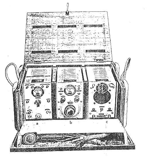
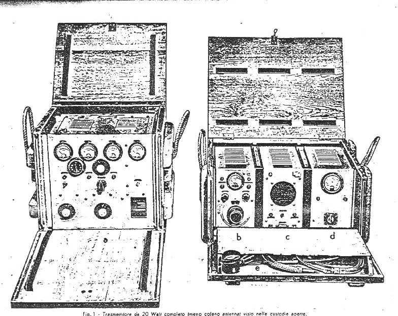
IMCA 20W
VHF Radio station. Used for point to point communication or like ground
station for night fighter ground control.
Year : 1940
Frequency Range : 59 - 64.5 MHz. Single channel Xtal controlled
Facilities : AM - Voice
Composition :
Receiver type IF
607
Receiver PSU IF 21S
Transmitter type SIM6020
AC Voltage regulator
RF Output : 20 W
Aerial : Vertical dipole
Power supply : By mains
R/200
Radio station. High power station used from Army Commands for long distance
communications. Separate receiver and transmitter.
Year :
Range 400 - 5000 Km
Frequency Range :
Receiver 1,300 - 20,978 kHz
Transmitter 3,750 - 15,000 kHz
Facilities : CW, MCW and RT
Composition :
Receiver: Superheterodyne type OC 8
Transmitter: R
200
PSU for TX, PSU for RX, Controll panel, storage batteries and engine
generator.
RF Output : 200 W in CW
Aerial : Vertical
Power supply : By mains (220 Vca) or engine driven generator suppling
220 Vca
10W UC
Radio station. Separate receiver and transmitter. Board set. Tank . Built
in Italy by Siemens under German licence. Communications range 2-5 Km.
Year : 1941
Frequency Range : 21.2 - 33.3 MHz
Facilities : MCW and RT
Receiver type : E 433Bs
Transmitter type: S 513Bs
RF Output : 10 W
Aerial : Whip
Power supply : 12 Vdc. By Dynamotor PSU, One for RX and one for TX
picture
