* * *
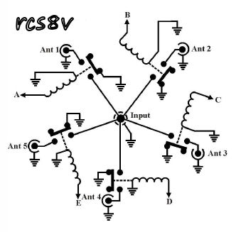
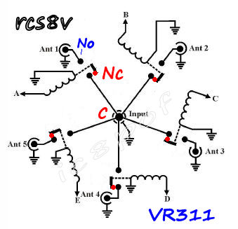
IC8POF's RCS8Vantenna switch mod. * * *
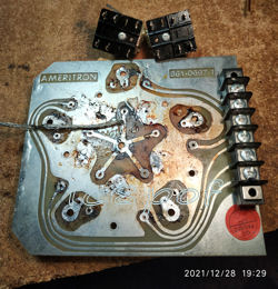
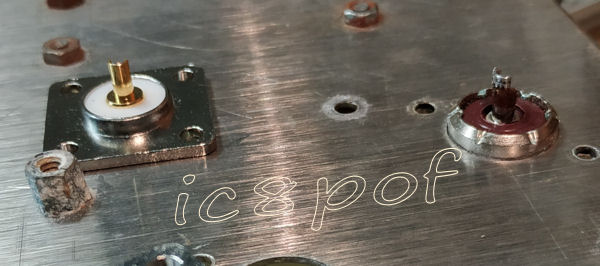
substitution of the old relays with the VR311 vacuum ones and the oxidized SO239s.

After many years of good work at my qth, a near marine enviroment, I have decided to substitute the old mechanical relays (still good)
and the SO239s due to their severe oxidation and the intermittent RF conductivity path ,
Here comes this almost easy add-on story.
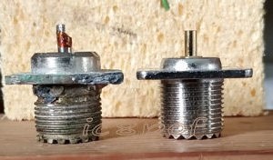
...this larger pic -> 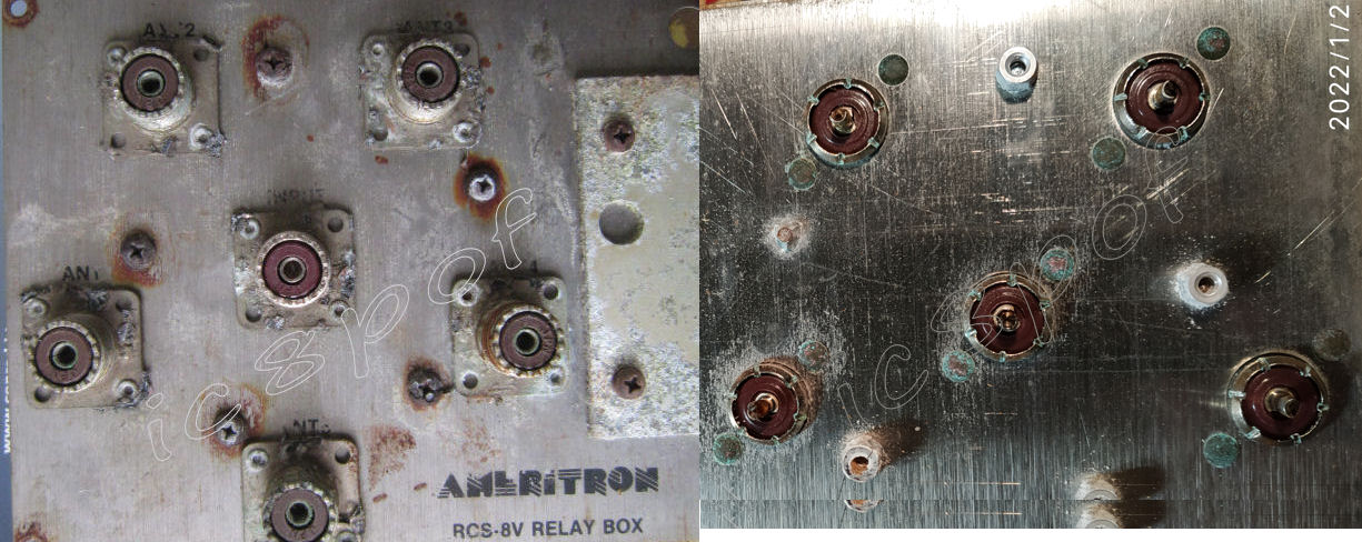 shows the severe oxidation of the SO239s and the holding rivets
that led to insufficient-intermittent connection between the connector's bodies
and the holding ground plate.

The rework is divided in two parts : Mechanical and Electrical .
due to the quantity of the original tin on the connections and some burns resulted in the pcb fiber.
Much better work resulted in the use of a medium soldering iron (70-80W)
and some pieces of the RG58 braid, which literally absorbs the heated tin when is put over it.
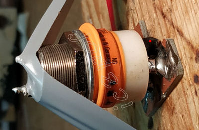
on the inner part of the holding plate to get the necessary height for the center
soldering pin and the relays board.
pic1
pic2
pic1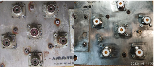 |
pic2 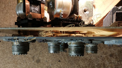 |
coat1 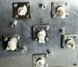 |
coat2 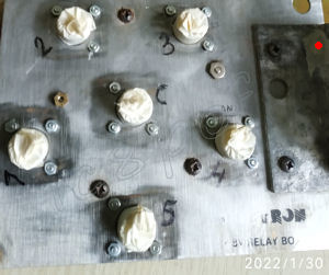 |
ground path  |
 pic2
pic2 
 pic4
pic4 
 |
 |
anti RFI upgrade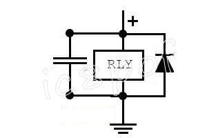 |
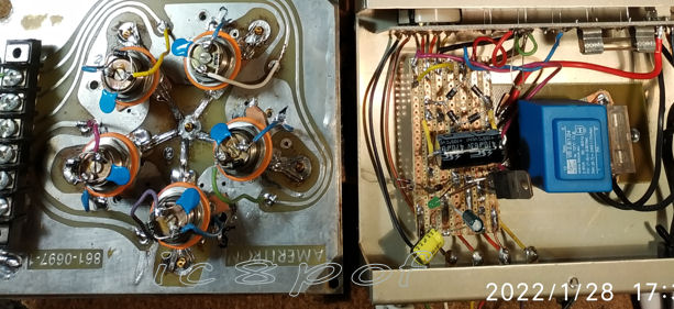
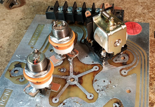
 shows how the new relays feet are connected to the old pcb.
Electrical part, reworking of the PSU. Last note : the front panel led indicators must be checked for a good light indication at a 1.5 to 2 Vdc working condition
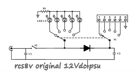
The original PSU schematic with a single diode could even be good, but the new transformator at almost 40Vdc out (1 diode no load)
could led to some too variable and unstable DC output voltage. To avoid this situation a small stabilizer is to be used.
The mounting of the transformator is done by the means of one isolating pcb, four feet for the trafo_pins and a 220vac fuse-holder.
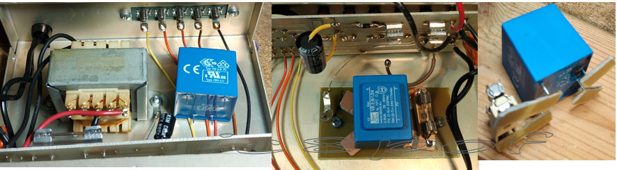
The transformer used (24vac\117mA) has enough current, but resulting in an unstable and critical load voltage with one rectifying diode,
hence the use of a diode bridge is quasi obliged, as the VR311 relays require 26,5Vdc at nominal 80mA of current.
I thought to use an LM317 stabilizer, but the drop from 40V out of the single diode to 30-34Vdc of the diode-bridge on load
was not sufficient to stabilize the required 26.5V output.
Therefore I discussed about the use of this transformer and what sort of stabilizer could be used with my friend Gian I7SWX
and he has suggested to try the following schema :
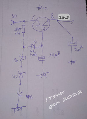
*** 24VAC trafo secondary output to a 4 diodes bridge + a transistor\zener stabilizer + the position led. ***.
new psu pcb ->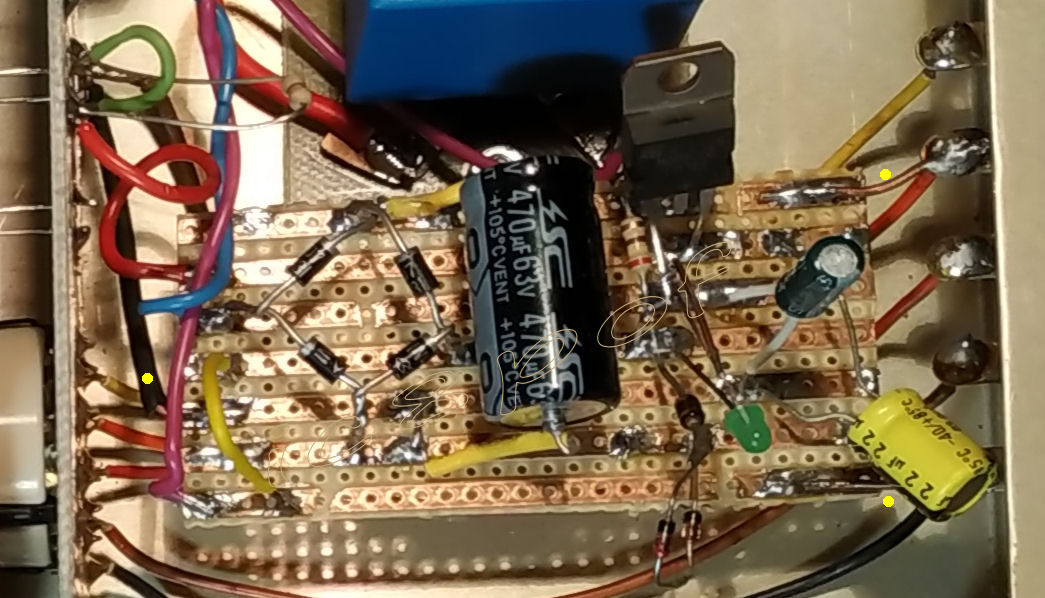 the yellow dots show the pcb mounting posts in the psu-box.
So I used what I had at stock and assembled the circuit as per schematic.
the 2 serial zener plus the 1N4148 deliver a voltage of around +-29 V,
the led diode (green gives circa 1.7V reduction) connected to the base (further -0.7V) and the transistor Vbe
give a resulting stabilized output at the Emitter of around 26.3/5V.
During the test phase I have discovered that not all the five relays had the same resistance but it ranged from 310 to 325 Ohm.
Of course the test has beeen carried with an in-lab 30 meters 2x0.34mm wires and the resulting total current drawn
from each relay ranged from 65 to 75 mA and summing the 10/15 mA of each position-led the total current is well
in the load range of the transformer used.
original psu
diode bridge
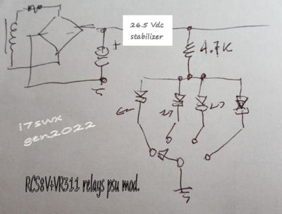
stabilizer
against the dropping resistor, in my case about 4000 Ohm and the new 26.5 Voltage.
I had to change two of them because did not light at all.
Of course the schema has worked well at once.
A big thankyou to my friend Gian I7SWX from the ideas and suggestions. mods & improvements by I7SWX.
Any improvement or suggestions will be appreciated,
write to my email on ic8pofATyahooDoOTcom (copy,paste and correct)
.
© v 1.00 feb\mar.2022