* * * new vacuum relais and bias switching * * *
TL922 Kenwood Amplifier
* * * new vacuum relais and bias switching * * *
This mod has seen the light because it was time to change that noisy rf and zener\lamps relais.

As usual a search in the web mare magnum has brought me on some good pages with lot of informations, but putting the substitution in practice is another thing.
That rig despite his oldness is still one of the best constructed piece of RF gear, rugged and compact, for those times a winner in the ham-radio market.
The goal was to use almost all the items I already had in my Lab, just the vacuums have been purchased.
All the vacuum relay schematics found in the web speak of QSK, even because the BIAS circuit has been modified to an electronic one,
but my decision was to keep the BIAS and the meter's lamps switchery via a common relais.
The main goal was to lower the switching noise of the old mechanical relais for the RF and the BIAS.
Now the PA has become almost unhearable.There would be still the fan noise, but this is another story.
The schematic is simple, two vacuum relais Siemens VR311 for the RF and one mechanical DPDT (poleA for BIAS and poleB for RX-TX lamps)
at 24Vdc coil are used in series, toghether with some resistors to get the proper drop voltages (green dots)
derived from the original relais supply at 100-110Vdc.
All the circuit has been tested for long TX times, couple of minutes, to ensure that the calculated drop would not produce too much heat.
If the PA should be used in RTTY or PSK, CW-HV and maximum 300Wout per mine experience, I would recommend to use 5W carbon resistors,
just to be sure that the heat of the divider resistors will be dissipated without risk of broking the Vdc line to the relais.
Of course the mounting places will be tighter.
During the testing phase one day the BIAS ZENER has decided to not more allow me doing dry tests so died and I had to change it with the more cheap
solution of the rectifying diodes 1N5401.
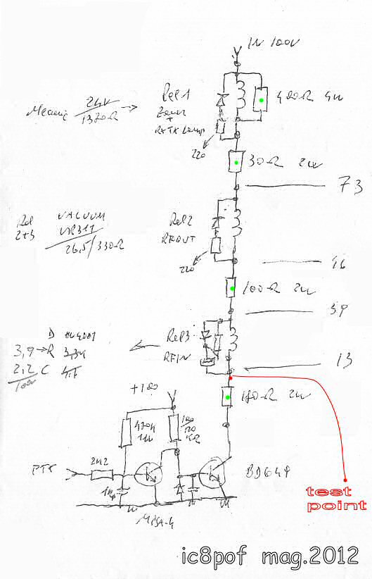
A red wire has been carried to the rear in the VAC compartment on a free lug as Check-Point to measure the remaining 13Vdc in the relais row
when the PA is put in TX
.

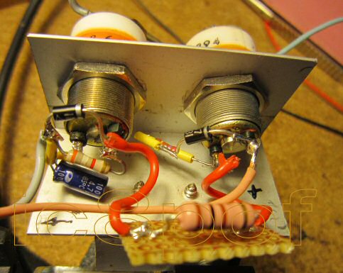
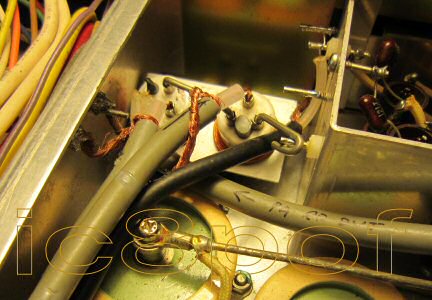
The pic below shows the relais bracket and the position in the chassis
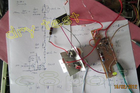
The whole mod is visible in the large pic, the pcb carrying the Relais1 and the resistor dividers is
completely removable for inspections or servicing.
link to larger pic. 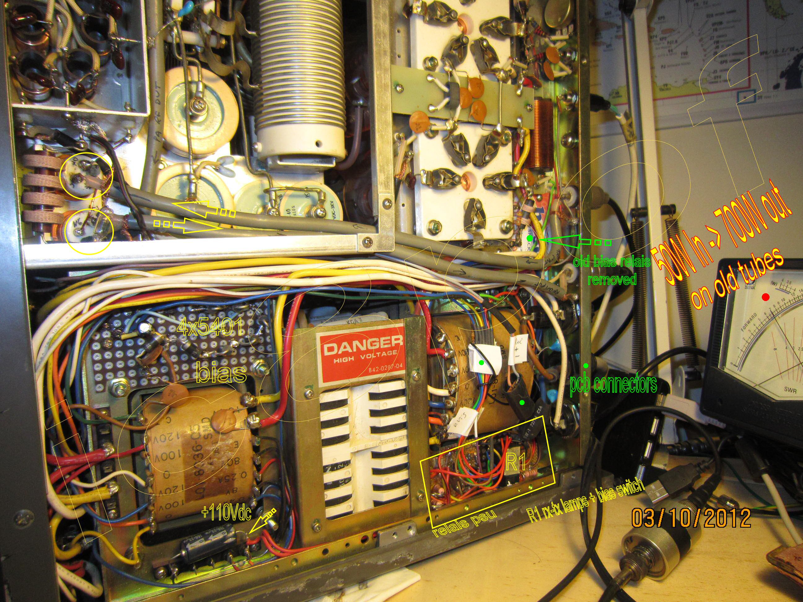
as the pic is very large to show all the corners, save it and view in your favorite picture manager.
Any suggestion to improve the schematic will be much appreciated.

mag.ott.2012