30mt new band mod. * * *

* * *
IC8POF's Commander Linear Amplifier
30mt new band mod. * * *
The story :
Since many years I was thinking if it would be possible to add the missing 30 meters band to this fine amplifier.
Studying the schematic once more at the beginning of december 2016 a LED switched (again) in my brain.
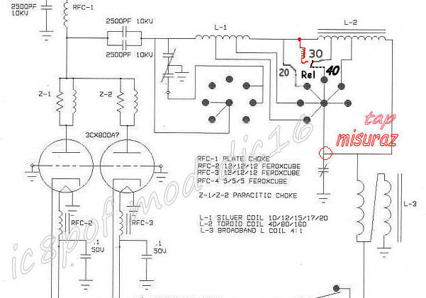
Looking at it every band portion of the RF_tank circuit has a piece of coil which closes to the LOAD_Capacitor,
leaving the other portions open.
Therefore adding a NEW coil with the right inductance for the 30 meters should be easy.
There were only some problems to be solved.
Your work will be much easier :-).
the problems :
 |
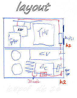
Problem a) : what for an inductance and switching relay should I use ?
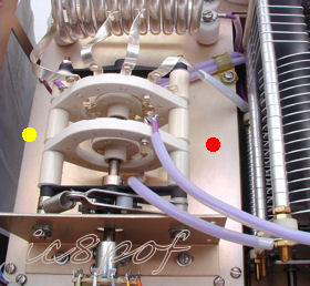
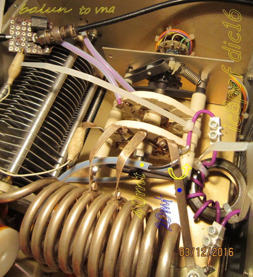
Look at the yellow dots, the right side(red-dot) of the BSU has no points to easy fasten a relay and a coil.
As the free space is very limited an Air_Coil even with few turns is out of discussion, so a toroid should be the best solution.
What for a toroid ? The L2 40-80-160 tank coil is made with 2xT225-2 toroids, but a short test with this large item
revealed the big difficulty to put such thing in the amplifier, so I decided for a smaller T200-2 already in the junk box.
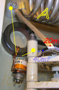
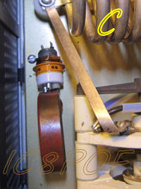
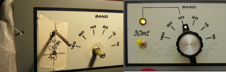
The decision to connect the new coil between the 20 and 40 meters side (pic A yellow dots) of the BSU is given by :
But nothing against a decision to use the 20 meters position.
Bear in mind only that the BSU contacts are not so strong as one could immagine
and are prone to broke. look here...PIN BROKEN
Remembering of the previous accident on the L2 ...follow this link...
I recalled that the turns for the 40 meters coil were 7, so the turns for the 30 meters should stay in a number
between 3 and 5 and I decided to start the tests with 6 turns over the T200-2.
 |
 |
... Cell 3- |
 |
link to larger pic 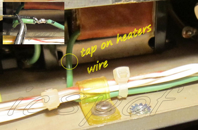 |
 |
-.-.-. |
link to larger pic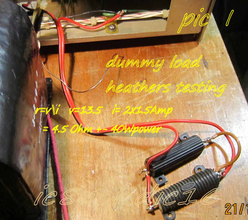 |
....... | -.-.-.- |
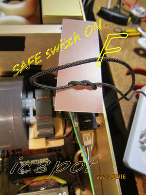
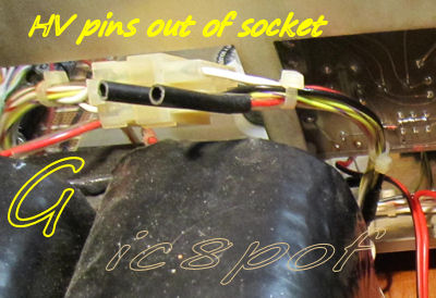
| To make the measurements on the T2 voltages, pre_checks for the voltage doubler and the functions of the new relay the amplifier must be left OPEN and running WITHOUT the plate voltage active That means that the T1 trafo is out of the box its connector is closed and HV pins have to be left open and the SAFETY switch has to be put in working position, look at pic F. |
 |
 |
c) d) TESTs & measurements:
Having solved almost all the hardware problems it was time to make some tests.
Problem f) the HARDWARE:
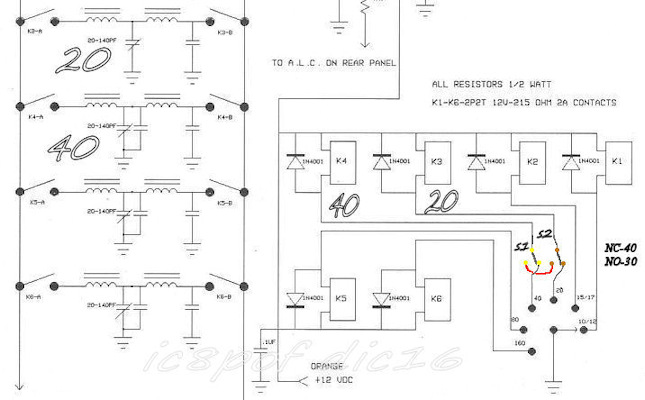
Look at the main schematic pic (TAP point+Ground)
at the beginning of this page.
link to larger view
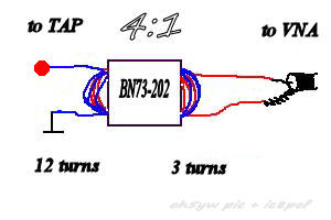
The idea to use an RF_analyzer to let me literally "see" where the PI_tank resonated
has turned around my mind
since long time and also a discussion with Gian I7SWX led to a conclusion that it should be again one of those
DO&TRY operations to see what happens.
The measurements with the analyzer have been done connecting it to the TAP point marked in the schematic above and pic E.
*** of course the PA is not connected to the Vac ! ***
Having seen that I can easily measure and "SEE" all the resonances of the PI_tank I have made a list for every band.
The following list shows why the amplifier did not resonate on 20 and 40 meters.
Frequency resonances
40 mt = 4.5 to 7.5 Mhz
20 mt = 12.7 to 16.8 Mhz
.
The following picture shows how strong was the resonance on 30mt with the new coil.
Of course the band_width is more than adeguate to cover the whole band in the SWR 1:2 edges.
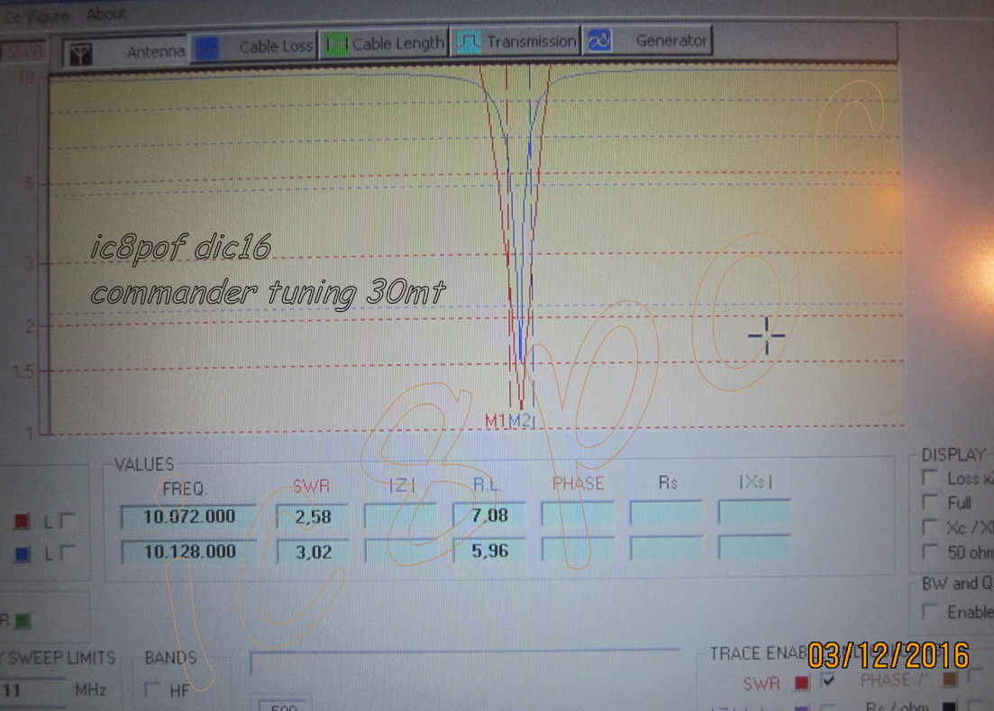
I had to try a couple of times by trimming the 30mt teflon wire and shorten the turns (finally 5) to get the
resonance in a place of the verniers where the PLATE and LOAD indicators should have a logical position somewhere
between 20 and 40 meters places.
Therefore the indicators had their final position at +-15 for the PLATE and at +-40 for the LOAD.
.....
After this first DRY TEST I decided to make an ON_AIR test but having in use ONLY the new 30 meter coil.
So a sort of 30mt MONO_band amplifier has been prepared to go ON_AIR.
The HOT_Test has shown that the idea of the new 30mt coil was a winning idea.
Problem e) the input PASSBAND:
which PASS_BAND input filter should be used for the new 30mt band: the 20 , the 40 or none of them ?
Therefore a flying DPDT switch has been prepared with the 20 and 40 meter pass-band switching cables to let manually
change the RF input (during PA St.By) and to look at the SWR between the TRX and the amplifier input.
The 40mt input filter had shown a high SWR more than 1:5 (very high one) and the 20mt had a fine 1:2 or less.
That mean that to activate the new band I needed a TPDT(triple-pole\dual-throw) with 1 pole to switch ON the relay and a signal led
and 2 poles for inverting the PASS_BAND wires during the 30 meters sessions.

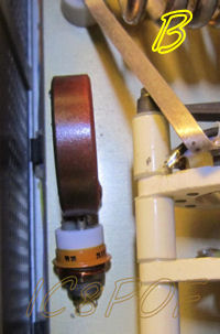
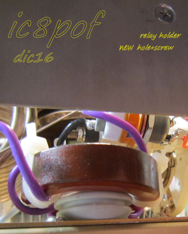
the toroid keeps firm itself by the mean
of the teflon wires,
but for a sure "not_moving" part
it is seated on a rubber button, look at pic D2
Remained to mount:
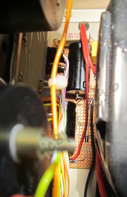
The voltage doubler board fits exactly between the HV trafo and the front panel below the IG meter.
link to larger pic 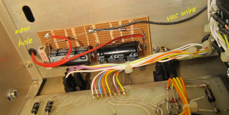
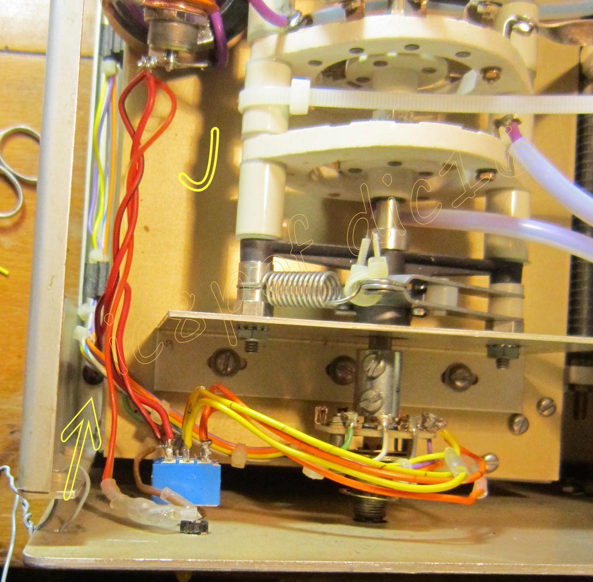
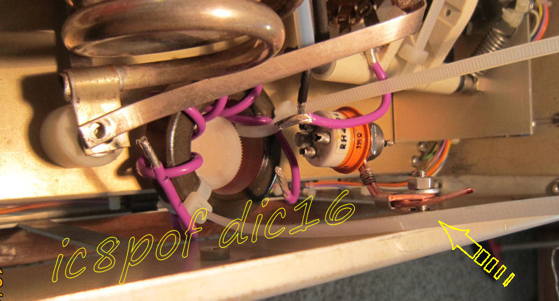
pic J shows where the psu wire comes up from H2 hole at the bottom of the chassis
and the new wires on the passband switcher.
I have used the same colors as the original for instant identification.
To better make the new holes the chassis is put upside down (sri no pics of it)
and after having marked the holes position, drill them.
To better study how to put inside the new hardware I have unmounted the front panel and the HV trafo .
The HV trafo must be taken out , but the front panel is not stricltly ncessary to be unmounted to do add this mod.
Problem g) HOWTO tune it:
Nothing special at this point, just follow the known procedures and keep the power to a reliable level
that is supported by the new coil.
The 1Kw level is easily reached. but the 6-700 Watt level is more than adeguate for a T200-2 toroid in CW.
For RTTY I think the power level should not exceed the 300W level.
Here the problem is the ventilation of the toroid in an already warm\hot environment,
but this is another story and another excperiment for the future mods.
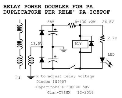
Here I want to thank my friend Gian I7SWX for his precious suggestions and for the voltage doubler idea. ... 
|
Any improvement or suggestions will be appreciated,
write to my email on ic8pofATyahooDoTcom (copy,paste and correct)
.