IN3OTD's web site
...under perpetual construction.

Some measurements on ferrite transformers
- 4:1 impedance transformer for small PA
- 4:1 impedance transformer for PA
- 1:1 impedance transformer for RX applications
- 50 Ω to 75 Ω autotransformer
- 50 Ω to 300 Ω transformer
- 5 turns / 4+4 turns transformer
4:1 impedance transformer for small PA
In the following a few 4:1 impedance transformers (50 Ω to 12.5 Ω) to be used as output transformers for a small HF PA are shown:
2:1, BN-43-202, for small PA
to check effect of low-impedance side wound with several wires in parallel
1x1t 2t
2x1t 2t
3x1t 2t
4:1 impedance transformer for PA
In the following a few 4:1 impedance transformer (50 Ω to 12.5 Ω) to be used as output transformers for a small HF PA are shown:
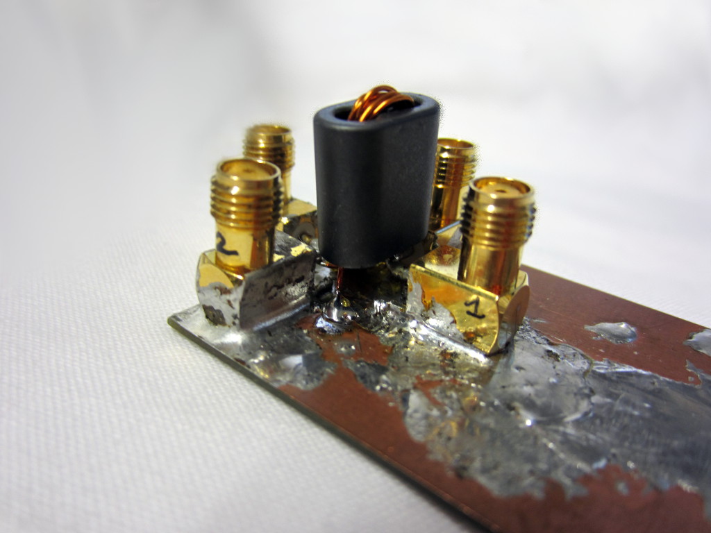
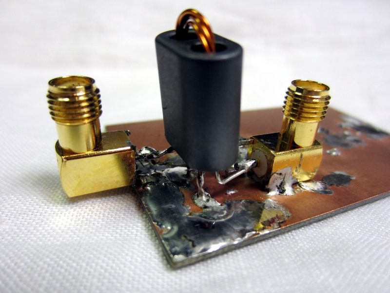
BN43-202_4_1_TLT_balun_1t_1t_2t_twisted_0.5_CT_no_GND.jpg
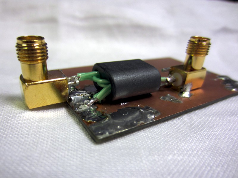
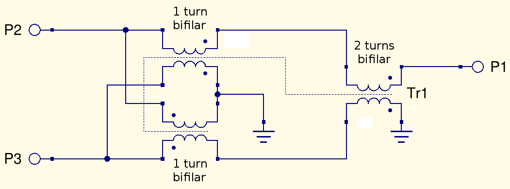
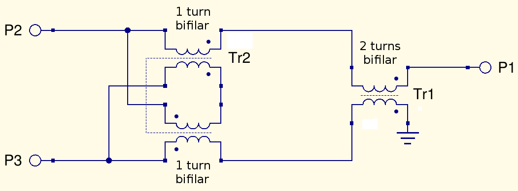
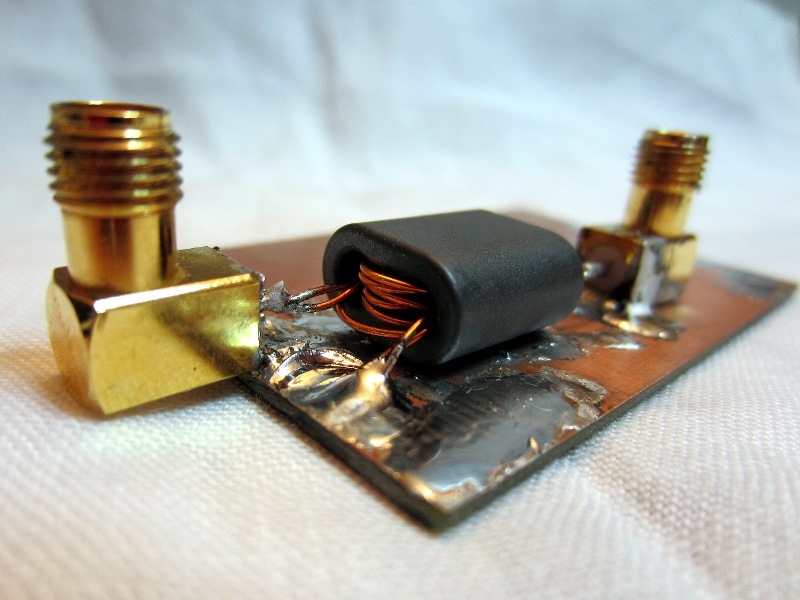
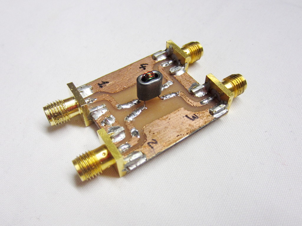
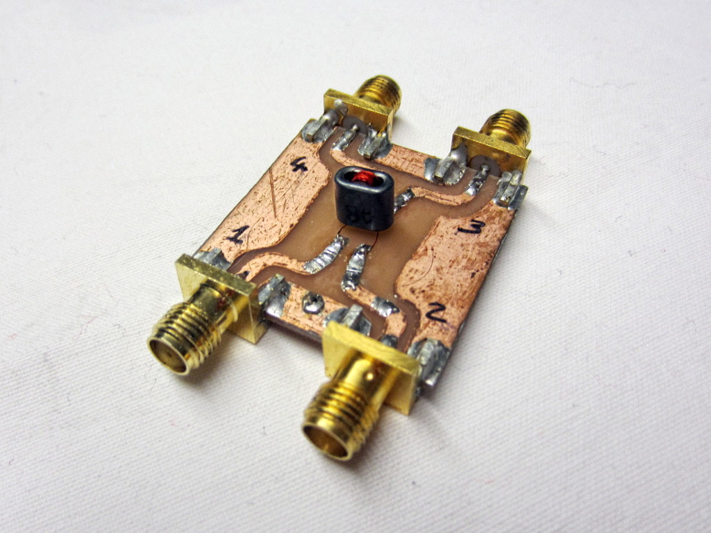
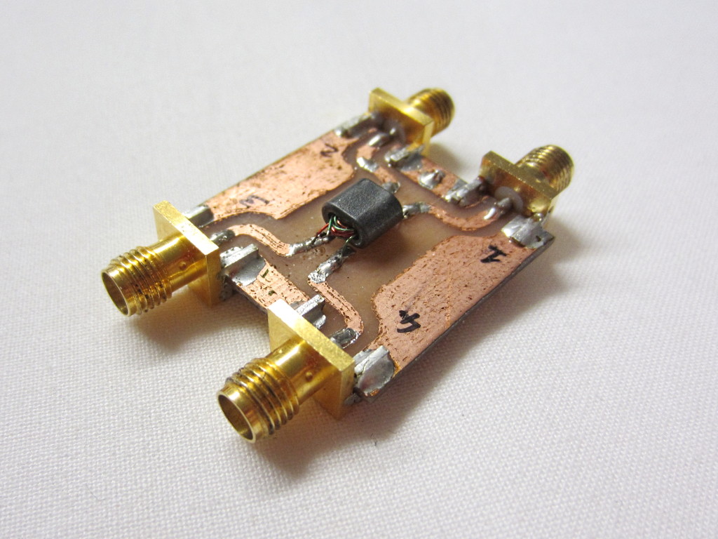
This is a 4:1 impedance ratio balun built with 2 x 1 bifilar turn plus 2 bifilar turns, all made with 0.5 mm diameter twisted enameled wire, on a single BN43-202 binocular core. The center tap is not connected.
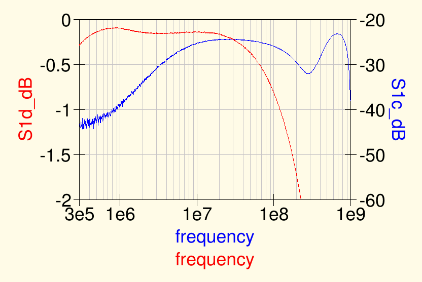
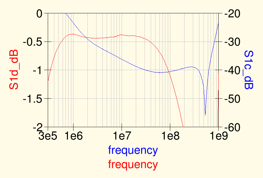
Philips Design of HF wideband power transformers APPLICATION NOTE ECO6907 http://www.radio-kits.co.uk/radio-related/Linear_PA/ECO6907.pdf Motorola AN593 Broadband Linear Power Amplifiers using Push-Pull TransistorsBN43-202_4_1_TLT_balun_1t_1t_2t_twisted_0.5_CT_no_GND_S1c_S1d.png
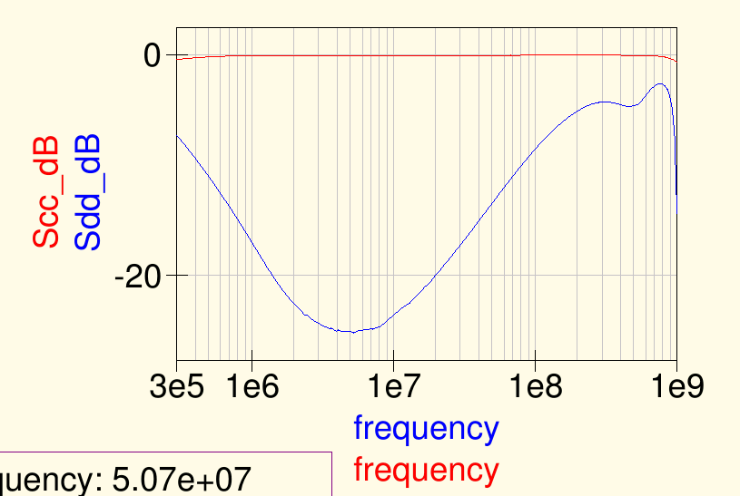
BN43-202_4_1_TLT_balun_1t_1t_2t_twisted_0.5_CT_no_GND_Scc_Sdd.png
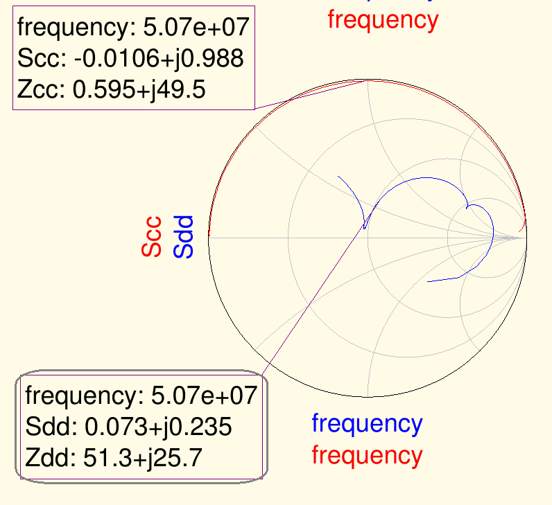
BN43-202_4_1_TLT_balun_1t_1t_2t_twisted_0.5_CT_no_GND_Scc_Sdd_Smith_chart.png
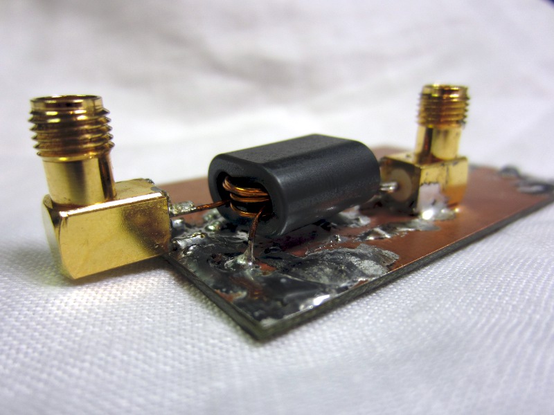
BN43-202_4_1_TLT_balun_1t_1t_2t_twisted_0.5_CT_GND.jpg
BN43-202_4_1_TLT_balun_1t_1t_2t_twisted_0.5_CT_GND_S1c_S1d.png
BN43-202_4_1_TLT_balun_1t_1t_2t_twisted_0.5_CT_GND_Scc_Sdd.png
BN43-202_4_1_TLT_balun_1t_1t_2t_twisted_0.5_CT_GND_Scc_Sdd_Smith_chart.png
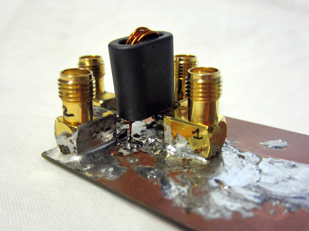
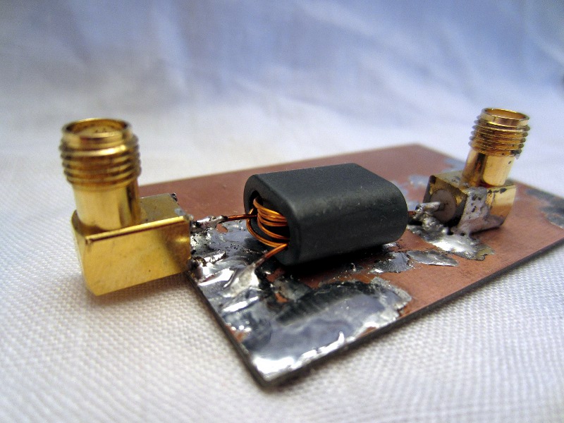
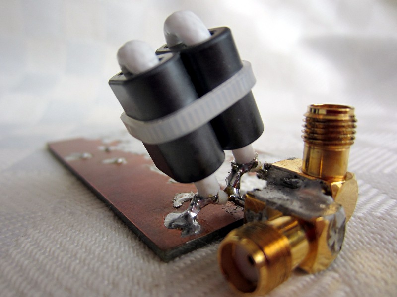
BN43-202_4_1_TLT_balun_CT_GND_2cores.jpg
BN43-202_4_1_TLT_balun_CT_GND_2cores_S1c_S1d.png
BN43-202_4_1_TLT_balun_CT_GND_2cores_Scc_Sdd.png
BN43-202_4_1_TLT_balun_CT_GND_2cores_Scc_Sdd_Smith_chart.png
BN43-202_4_1_TLT_balun_CT_no_GND_2cores.jpg
BN43-202_4_1_TLT_balun_CT_no_GND_2cores_S1c_S1d.png
BN43-202_4_1_TLT_balun_CT_no_GND_2cores_Scc_Sdd.png
BN43-202_4_1_TLT_balun_CT_no_GND_2cores_Scc_Sdd_Smith_chart.png
BN43-202_2x1t_2t_twisted_0.5.jpg
BN43-202_2xTLT_twisted_0.5.jpg
BN43-202_1t_2t_coax_FEP.jpg
BN61-202_2t_4t_0.5.jpg
BN-43-202_1x2t_6t_enameled_0.5.jpg
BN-43-202_2x2t_6t_enameled_0.5.jpg
4:1 Ruthroff impedance transformer for small PA
4:1 Ruthroff impedance transformer
BN-43-202_Ruthroff_4_1_0.4mm_bifilar_2t.jpg
BN-43-202_Ruthroff_4_1_0.4mm_bifilar_2t_S21.png
S-parameters fileBN-43-202_Ruthroff_4_1_RG316_1t.jpg
BN-43-202_Ruthroff_4_1_RG316_1t_S21.png
S-parameters file1:1 impedance transformer for RX
BN-43-2402, 1:1, 2x20 turns
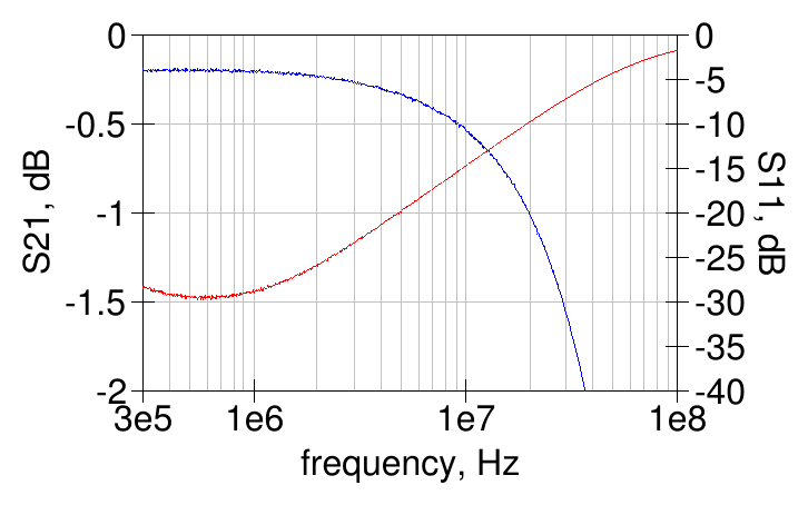
Out of curiosity, I wanted to check if a transformer with performances similar to the MiniCircuits T1-6T could be made with a BN-43-2402 core; about 20 turns are needed to have the same low-frequency inductance as the T1-6T (about 650 uH), so I wound a BN-43-2402 core with 2x20 turns of 0.1 mm enameled wire (not twisted); the fine wire is needed to make all the turns fit, it won't be easy to fit 2x20 turns with a larger wire.
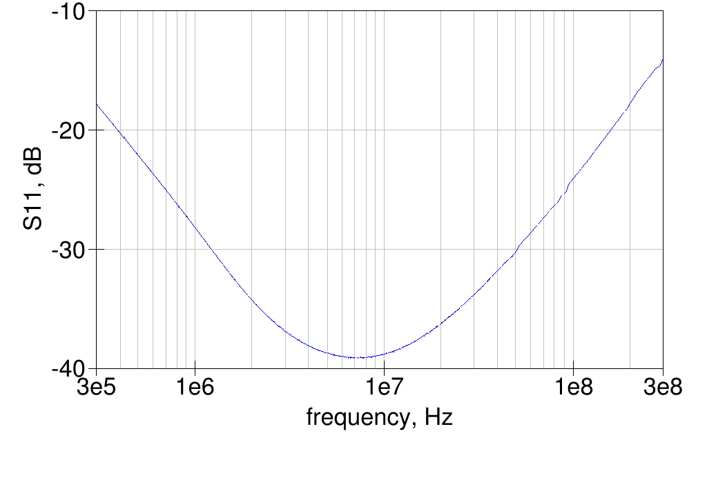
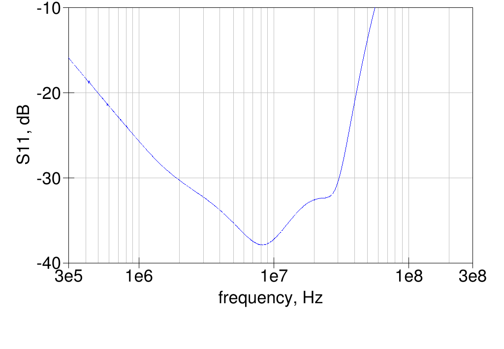
Measured on a VNA, it turns out that the low-frequency response is very similar to the T1-6T, as expected, but the high-frequency response is quite worse, at 60 MHz the losses are about 2.2 dB and the return loss is only 5.5 dB - this was somewhat expected with all the wire and turns needed. The following graph shows the measured insertion loss and return loss. S-parameters fileBN-43-2402, 1:1, 2x8 turns
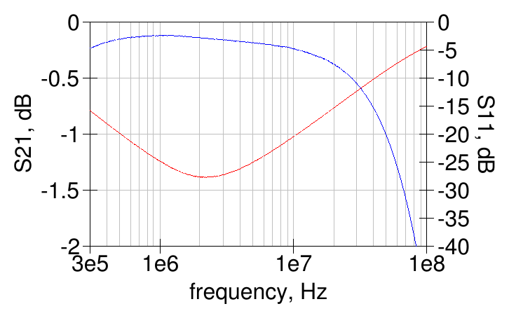
Transformer as above, but with just 8 turns per winding, to improve the high-frequency response.
 S-parameters file
B64290P 0732x038, 1:1, 2x15 turns
Another attempt at a wideband transformer, using a very small core (about 4 mm diameter) to reduce the lenght of the wire used and improve the high-frequency response.

in the picture above the upper scale is in inches (0.025″ per division) and below in centimeters (1 mm per division)
S-parameters fileBN-43-2402, 1:1, 2x5 turns
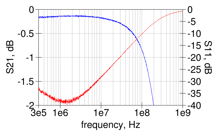
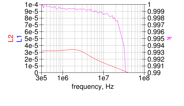
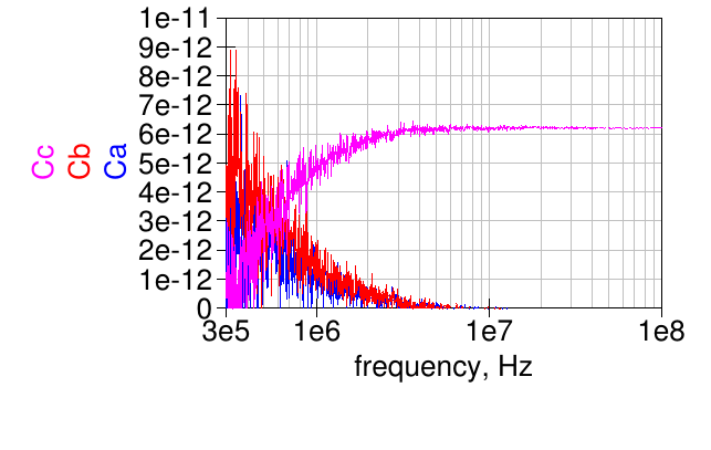
BN43-2402 core with 2x5 turns of 0.25 mm (30 AWG) enameled wire, lightly twisted.
Inductance and coupling factor:
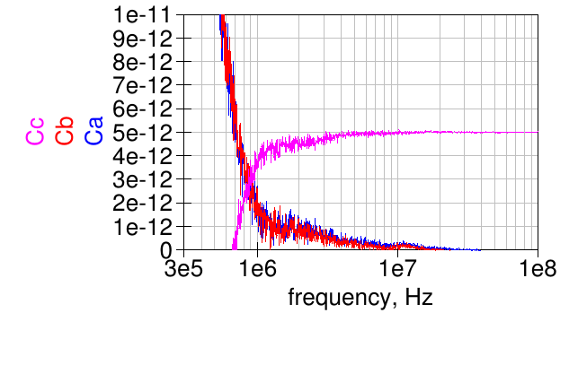
Windings capacitances:
FT50-75, 1:1, 2x5 turns
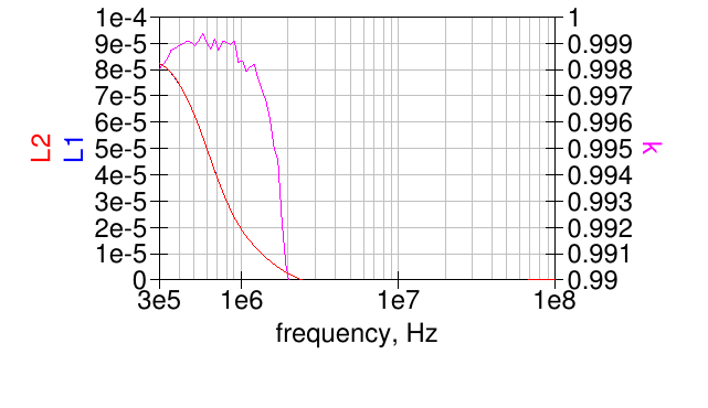
FT50-75 core with 2x5 bifilar turns.
Inductance and coupling factor:
Windings capacitances:
FT50-43, 1:1, 2x5 turns
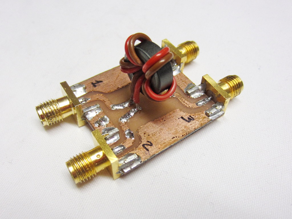
FT50-43 core with 2x5 turns of 0.25 mm (30 AWG) enameled wire, bifilar/lightly twisted.
Inductance and coupling factor:
Windings capacitances:
BN43-2402_2t_4t.jpg
50 Ω to 75 Ω autotransformer
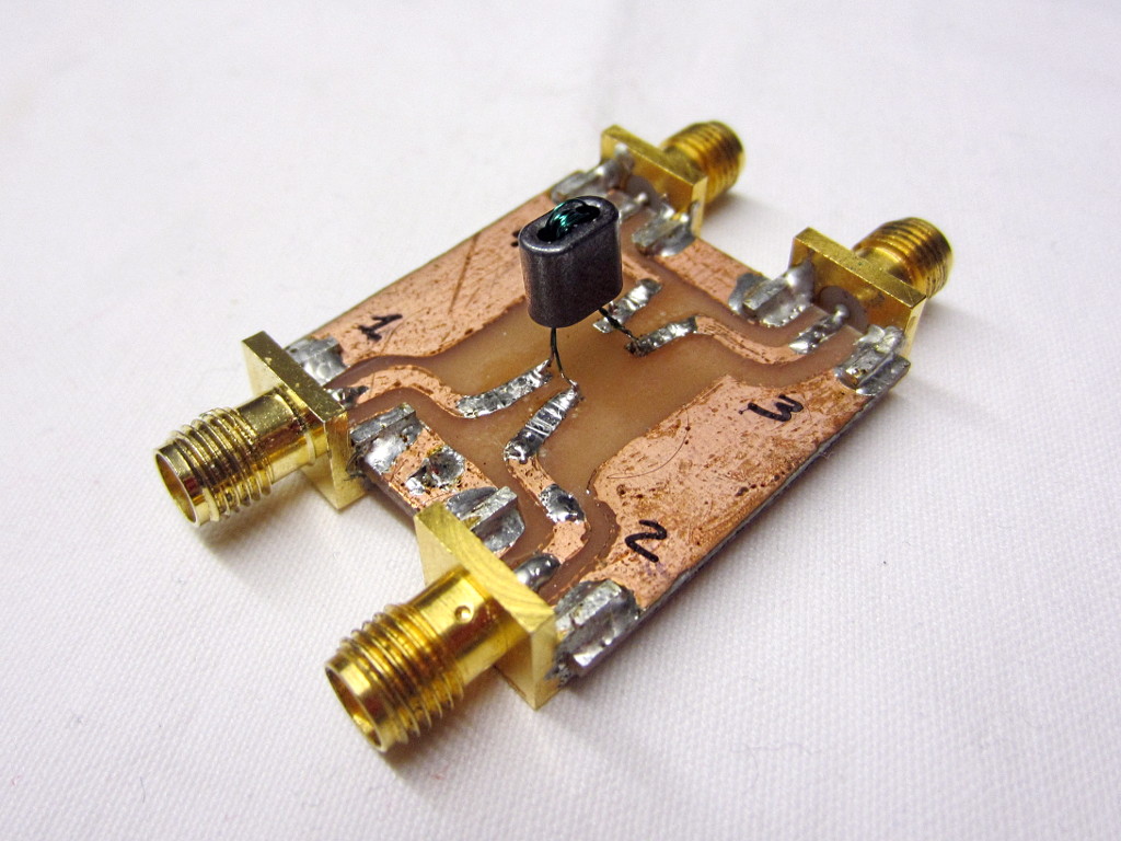
Autotransformer from 50 Ω to 75 Ω with 9 turns on the low impedance side and additional 2 turns to the higher impedance side, on a BN-43-2402 binocular core.
S-parameters fileS-parameters file (all terminals floating)
50 Ω to 300 Ω transformer
Transformer from 50 Ω to 300 Ω (floating) with 8 turns on the low impedance side and 20 turns on the high impedance side, on a BN-43-2402 binocular core.
S-parameters fileBN43-2402, 5 turns / 4+4 turns transformer
5 turns / 4+4 turns transformer on a BN43-2402 core to be used as input transformer to a small push-pull power amplifier< /p>
BN43-2402_5t_0.2mm_4t+4t_0.25mm_S1c_S1d.png
BN43-2402_5t_0.2mm_4t+4t_0.25mm_Scc_Sdd.png< /p>


