24GHz Equipment
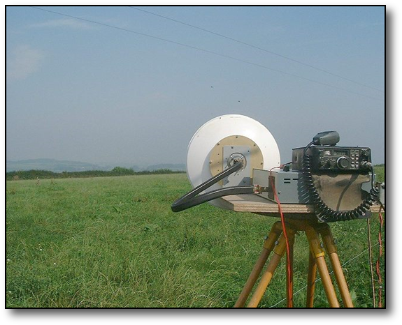
The equipment mainly used portable comprises a 30cms ex-link Cassegrain dish, plus a homebrew transverter with a 145Mhz IF based on the DB6NT, design but incorporating an ex- link equipment amplifier to bring the Tx power up to 400mW. The receive amplifiers use cheap readily available GaAs fets type NE325 by NEC for use in SATV LNB equipment. (The lossy flexible waveguide is no longer part of the system!)
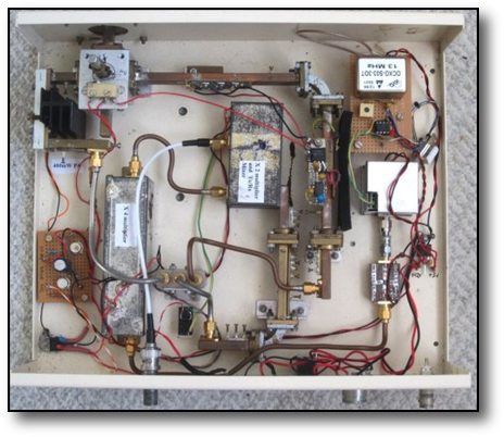
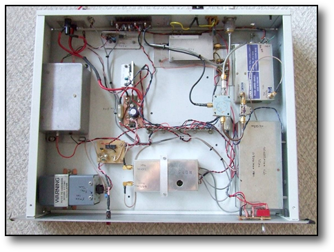
The internals of the 24Ghz transverter. On the extreme left is the 400mW PA with black heatsink attached and below that the relay drive circuit on Veroboard. The PA is attached to the manual waveguide switch which also has the two receive amplifiers (on copper WG20) on the opposite port. The third and fourth ports terminate the antenna and a WG 20 load. A coaxial 3 port switch, near the middle of the picture, is used to select the input to the PA or output of the receive amps for the input/output of the DB6NT transverter and waveguide filter shown near the center This switch is electrically ganged by a microswitch on the waveguide input / output switch. Adjacent to the switch driver is the WDG009 11Ghz multiplier. An upgrade has been to replace the crystal OCXO and to install an LMX2541 synth. which runs at a frequency of 2987.875Mhz and derives its reference from a 13MHz OCXO shown top right. The synth. is followed by a MMIC amplifier to raise its level to +10dBm, enough to drive the following X4.
Listen to a typical SSB QSO with GW3FYX/P over a 60km path ..(a slight bit of drift on the FYX LO!)
Listen to a typical SSB QSO with GW3FYX/P over a 60km path ..(a slight bit of drift on the FYX LO!)
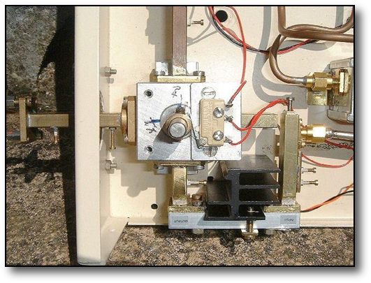
The photo on the left shows in detail the mounting of the 24GHz "PA", with the all important 10BA tuning screws at the input and output of the PA plus, also on the output wavguide (extreme left) prior to the antenna and after the WG switch. These screws were worth another 80-100mW after their addition. This view also shows the tapered WG20 transitions at both input and output plus the heatsink which is clamped to the "non labeled" face of the PA module, to conduct heat away from the internal substrates.
High stability and good phase noise are a must at 24Ghz and upwards. Thus the crystal used in the LO must be of high quality and age predictably. Several suppliers have been tried for crystals and those supplied by Eisch-Kafka in Germany from a company called QT seem to be currently the prefered type. These are usually specified for operation with an oven temperature of 60degC. If stabilty is poor then even the best PLL will not hold the crystal in lock, and if the crystal has poor phase noise then a "burble" will be evident on the signal, rendering SSB unintelligible in the worst case.
High stability and good phase noise are a must at 24Ghz and upwards. Thus the crystal used in the LO must be of high quality and age predictably. Several suppliers have been tried for crystals and those supplied by Eisch-Kafka in Germany from a company called QT seem to be currently the prefered type. These are usually specified for operation with an oven temperature of 60degC. If stabilty is poor then even the best PLL will not hold the crystal in lock, and if the crystal has poor phase noise then a "burble" will be evident on the signal, rendering SSB unintelligible in the worst case.
Surplus equipment modification
Just recently some surplus commercial equipment has come on to the market from Alcatel. Some types of this equipment will go directly on to 24Ghz while other types of the same equipment are made for the 22-23Ghz and need modification. G4NNS also has some further information on his website here on how to integrate seperate modules into a complete transceiver.
Conversion details are mainly in French courtesy of F6DRO, although I can e mail a cryptic translated version in English.
There are also some 23GHz units around by Thales, modification for which can be found here courtesy of VK2TDN.
Conversion details are mainly in French courtesy of F6DRO, although I can e mail a cryptic translated version in English.
There are also some 23GHz units around by Thales, modification for which can be found here courtesy of VK2TDN.
A 24GHz Beacon Monitor Receiver
A recent addition at home has been to add a receive only system on the mast, primarily to monitor propagation on the GB3SCK beacon mentioned below.
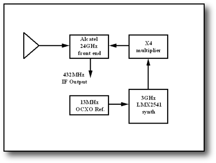
The block diagram on the right shows the basic configuration of the unit.The system uses a 432Mhz IF and while it is not the ultimate in rx systems, as it has no image rejection filter, it seems to suffice for beacon reception just with the small horn shown on the right and exhibits a NF of ~ 2.5dB. The main front end receive module is the GBY111 module from the 24GHz Alcatel system mentioned below, which requires an ~11Ghz LO input at +13dBm. Frequency stability, spectral purity and phase noise is excellent using a TI LMX2541 synth chip driven by a surplus KVG OCXO which just happens to be on 13MHz. (The synth. can be programmed to accept any ref. frequency)
The block diagram on the right shows the basic configuration of the unit.The system uses a 432Mhz IF and while it is not the ultimate in rx systems, as it has no image rejection filter, it seems to suffice for beacon reception just with the small horn shown on the right and exhibits a NF of ~ 2.5dB. The main front end receive module is the GBY111 module from the 24GHz Alcatel system mentioned below, which requires an ~11Ghz LO input at +13dBm. Frequency stability, spectral purity and phase noise is excellent using a TI LMX2541 synth chip driven by a surplus KVG OCXO which just happens to be on 13MHz. (The synth. can be programmed to accept any ref. frequency)
24GHz Beacon Project -GB3SCK
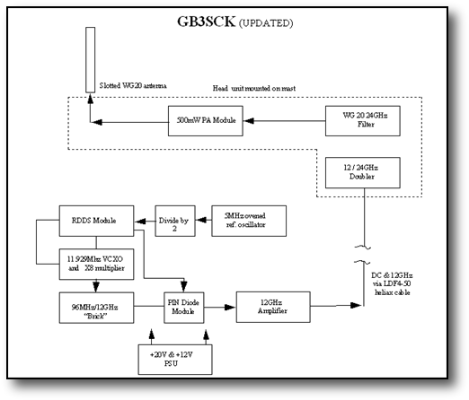
A number of beacons are co-located on the south coast at IO80UU, one of which is a 24Ghz beacon built by myself. The block diagram is shown here and more details can be found at the beacon website given below, where you can also donate to the upkeep of the complex unit. I took the opportunity in October 2013 to replace the WA6CGR PLL with an RDDS module which allows the use of the JT4G mode, enabling the beacon to be detected under very weak signal conditions.
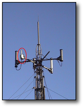
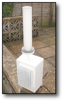
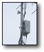
The 3 pictures here show the "indoor unit", the head unit and radome and the head unit mounted on the mast.
Visit the South Coast Repeater and Beacon Group site at www.scrbg.org to read more about my beacon
Listen here to the beacon over a 40km path on rainscatter
Listen here to the beacon over a 40km path on snowscatter
Visit the South Coast Repeater and Beacon Group site at www.scrbg.org to read more about my beacon
Listen here to the beacon over a 40km path on rainscatter
Listen here to the beacon over a 40km path on snowscatter
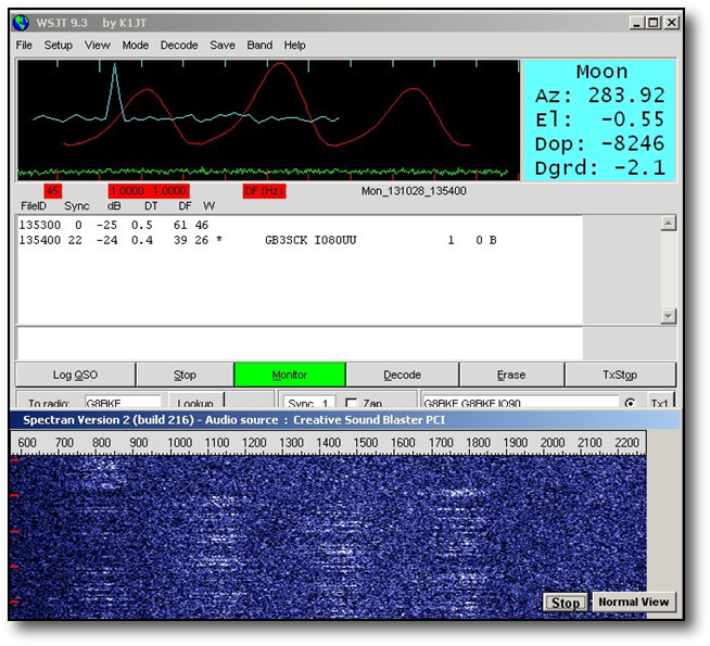
Following the recent upgrade to JT4G mode, an onset of heavy rain meant the beacon became audible over a 40km path on rainscatter. The screen grab on the left clearly shows how resilient this mode is under such conditions when a perfect decode was made despite the wide dispersion on the signal shown.
During 2023 the signal from the beacon became very weak, so while the site mast was lowered it was removed for repair. It was found that the nominal 1 watt PA output was very much reduced to only 30mW after 20 years of continuous operation!. Examination showed a number of tiny flies had gathered in the output guide of the PA. This probably did nothing for the match and the PA eventually succumbed. A new PA was duly sourced.
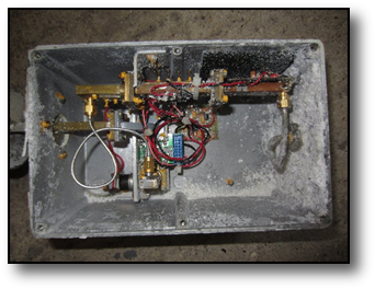
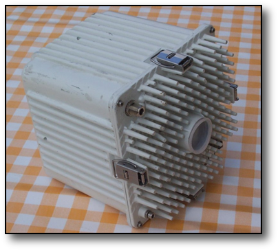
The internals of the sealed head unit box had suffered a bit from condensation over the years as can be seen in the picture below, although electrically they seemed to still function okay apart from the PA.
A 24GHz "First"?
Way back in February 1996 on a visit to my parents in GM land I took the 24GHz kit with me. The aim was to have a contact with GM8BJF in Edinburgh from the hills above Bathgate.
As I recall the contact over 25km LOS path (easy by todays standards!) went well and was the first time we had worked one another, both with new homebrew kit. What we didn't realise at the time was it was the first GM to GM contact on the band!
During the contact it actally started to snow, but then who on earth tries /P operation in GM in February!!!
