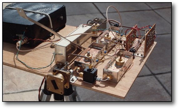
10GHz Narrowband Equipment
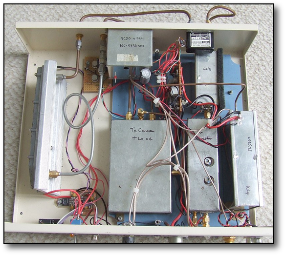
The Mark 2 NB equipment shown on the left comprised a basic G3WDG transmit and receive system with the addition of a 1W Qualcomm amplifier. An G8ACE ovened oscillator with a Luis Cupido type PLL was used for the LO and this can be locked to a 10MHz GPS locked source. Another solution would be to use a REVDDS system. Its a pretty horrid looking assembly of parts as it "grew" over the years and was re-boxed several times, the last time to accomodate the 1W Qualcomm PA seen on the left.
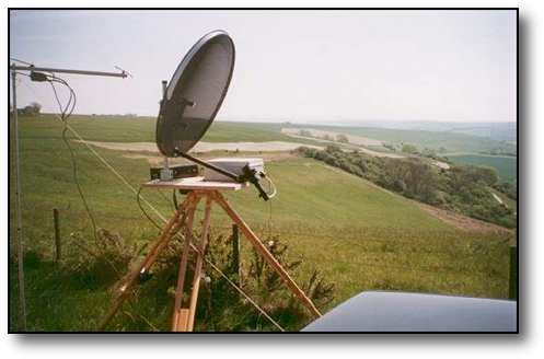
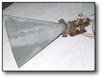
For portable operation a 60cm offset antenna shown here, was used with a dual mode feed. Best Dx with this gear was 350km while out /P. With signals also copied off the moon, when the 20m dish at Bochum in Germany was activated with 200W!
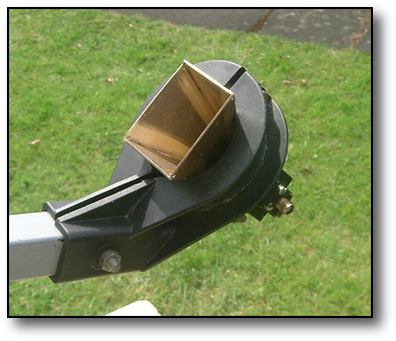
A better design of feed horn by G4NNS was tried instead of the dual mode feed.
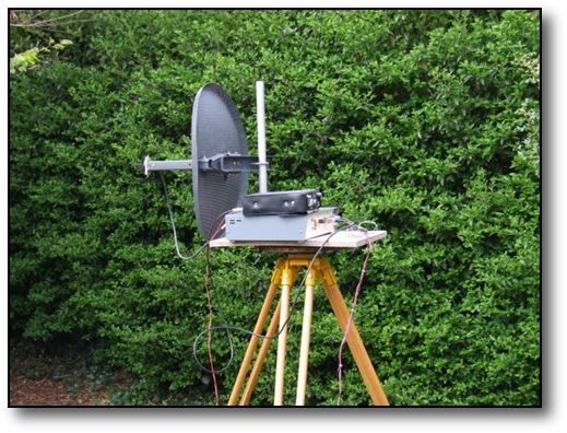
Some experiments were tried looking at the more compact "Sky" dish....shown on the right. This was tried with the same dual mode feed for 10Ghz and also a dual band feed for 10 and 24Ghz. To reduce pointing problems associated with getting the elevation correct, the dish was used at 90degrees to its normal operating position.
A Simple 10GHz Transverter
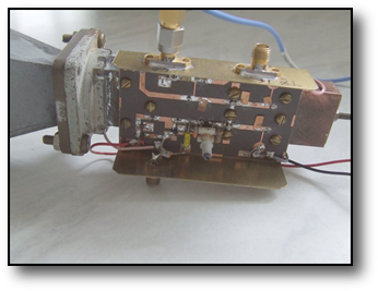
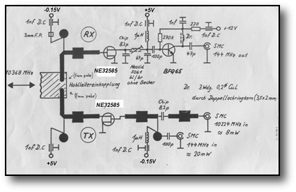
Some experimentation was done with a very simple 2-GaAs FET transverter. This was published in the March 1989 Microwave Newsletter from a German design way back in the late 80's by DC0DA, but updated here with some more modern components. Output power was about 0.8mW and it gave a good account of itself on a single 20dB gain horn on both receive and transmit. Of course the performance was not up to a fully fledged transverter but creditable nevertheless and despite the low output power it can be classed as a "narrowband system" thus benefiting from the gains one gets over a wideband system of frequency stability and narrow operating bandwidth. The pcb was made on 0.79mm Teflon PCB with Er = 2.55 and of dimensions ~ 40 x 70mm. The power supply required was +5V and -1.5V. A suitable circuit operating from 12V is shown on page 18.108 of the RSGB Microwave Handbook Volume 3,using a 3 terminal 5V regulator and a 7660 negative voltage generator. If serious operation is contemplated, it would be advisable to fit a WG16 filter tuned to 10368.1Mhz ahead of the unit to prevent radiation of the LO frequency.
In addition to the parts shown here, one would need an LO producing 10224Mhz output at about 8mW from a 106.5Mhz crystal. This can be obtained from a xtal oscillator, a X24 multiplier and a X4 multiplier. Or one can convert a 12GHz DB6NT LO/ multiplier module to 10Ghz as shown in the October 2009 Scatterpoint, or via a ADF5355 chip described later on this page.
In addition to the parts shown here, one would need an LO producing 10224Mhz output at about 8mW from a 106.5Mhz crystal. This can be obtained from a xtal oscillator, a X24 multiplier and a X4 multiplier. Or one can convert a 12GHz DB6NT LO/ multiplier module to 10Ghz as shown in the October 2009 Scatterpoint, or via a ADF5355 chip described later on this page.
Wideband 10Ghz Equipment
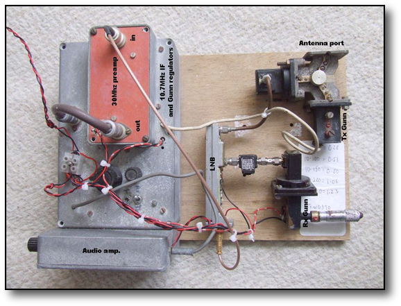
The equipment to the right is a Mark 2 version of that used in the 1970 and 80's. The Mark 2 version receiver comprises an ex-SATV LNB with the the DRO disabled and image filter by-passed. The output from a tunable Gunn oscillator is injected into the mixer via an isolator to reduce frequency pulling. The Gunn cavity is coarse tuned with a micrometer in the cavity with fine tuning done by varying the Gunn voltage +/- 1volt via a potentiomter. The IF output from the LNB is at 30MHz and this is amplified in a 30Mhz preamp before being down converted to 10.7Mhz where FM detection takes place in a standard wideband FM frequency discriminator.
The Tx side comprises a fixed tuned Gunn oscillator generating approx. 10mW output on 10.15GHz. This is FM modulated with either speech or an audio tone.
Coupling of both the Tx and Rx to the antenna is via a waveguide 16 circulator.
The Tx side comprises a fixed tuned Gunn oscillator generating approx. 10mW output on 10.15GHz. This is FM modulated with either speech or an audio tone.
Coupling of both the Tx and Rx to the antenna is via a waveguide 16 circulator.
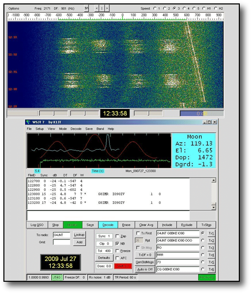
JT4G digital mode at 10GHz
Some tests were made, receiving JT4G from G8IMR/G4JNT over a 32km partially obstructed path, under rainscatter conditions to investigate how well the mode stands up to anomolous propagation. As can be seen below, despite the signal being severly doppler shifted due to the heavy rain between the two stations, copy is still 100%
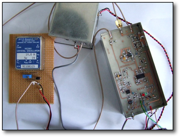
Generating JT4G on 10GHz
The set-up shown left shows bench testing of a test signal source using a G8ACE 108MHz OCXO locked to a 10Mhz standard via a prototype RDDS module equipped with a PIC to generate a JT4G signal. This was then multiplied up to 10Ghz in a DDK004 source and WDG X4 multiplier. Accurate timing was produced by linking the RDDS module via its RS232 serial link (blue / green wires) to a Jupiter GPS system.
For some years I was active on 10Ghz before migrating up to the higher bands. The equipment shown below is what I used.
However.......with the appearance of the ADF5355 synth on the market with a low power 10GHz output the appeal of producing a low powered 10GHz signal locked to an OCXO needing no multiplier stages to get from a lower frequency crystal, seemed even more appealing especially as it can cope with digital modes such as JTG4 or PI4.
Even without the modulation and programmed to an output of 10224 rather than 10368MHz it could be used to provide an LO for the simple transverter described elsewhere above.
This picture here shows a breadboard set-up of a trial of such a system. Note the lack of multiplier stages needed, the output going straight to the PCB antenna at about -13dBm. Also in the picture is the OCXO top left, a NEO module bottom left to provide a GPS timing signal and a bias T network to feed a GPS antenna.
In the picture bottom right is a small Arduino module used to drive the SPI interface of the synth to provide the frequency info to the chip and also the digital modulation of, in this case JT4G. However there is never a free meal as with all these digits around, noise and key clicks can be a problem which can appear on the final signal, so as a temporary fix the synth signal leads are shrouded in cooking foil, which togther with other fixes can contribute to further reduction of noise and click suppression (see comments from GM8BJF here for more info on this)


The picture here is a similar sort of source driving a Qualcomm amplifier, shown left with only a small amplifier "culled" from a popular surplus LNB, in between to raise the level to +3dBm to drive the amplifer to +29dBm output. Here the synth is driven by a PIC and uses its own on board XCO for test purposes (more details here)

This is the Mark 1 version of my 10GHz kit which used a simple diode mixer in waveguide 16 on receive and a cross-coupler but still achieved contacts in excess of 150km.
This was the first attempt at 10GHz narrowband.
Modules made in tin boxes from a design I believe was in Dubus at the time. It ran a few 10's of milliwatts and had a noise figure of goodness knows what!. But an improvement over the wideband gear used until then.
Modules made in tin boxes from a design I believe was in Dubus at the time. It ran a few 10's of milliwatts and had a noise figure of goodness knows what!. But an improvement over the wideband gear used until then.
3Watts at 10GHz
Recently Mini Circuits has introduced a chip which is rated at 3W out with 30dB gain; the PMA5-123-3W. This offers a much smaller footprint than the Qualcomm described above.
The opportunity arose to obtain a chip from the US complete with a pcb via Kent WA5VJB. There is quite a bit of constructional info online courtesy of Maarten PA0MHE who had already made a nice job of trying the chip out...... so it was decided to give it a try.
After struggles with the tiny chip components, after some Valium, the board was eventually populated, but it needed a bias arrangement to ensure that the main +7V supply did not appear before the gate voltage! Luckily Maarten had been there too and had devised a cunning arrangement to do this. The Gerber file for that pcb was made available and through Steve G4HSK who was doing the same project a few pcbs were made in the Far East and quickly shipped to the UK..more tiny chips components!


Eventually the two boards were connected together as shown below and the big power up day was near. A small ally block was obtained and the RF pcb mounted on it. Circa +10dBm at 10GHz was made available from an ADF5355 synth.
Initial findings were disappointing as both Steve and I had less than 1W output. After much head scratching it was found that mods to the pcb were needed. It also highlighted that to get useful output the boards might benefit from being in a metal enclosure and also on a decent sized heatsink if prolonged operation was to be considered. The quiescent standing current was also increased to increase the gain to something like what was quoted.
It was Steve to the rescue again using software to generate CNC files for a nice milled enclosure. Currently one sample was produced and needed slight modification to stop instability but the good news is that it seems to produce 2.5W
Subsequently I ordered a housing which is shown left here, fitted out with the 2 pcbs and is under test.
