76GHz Equipment
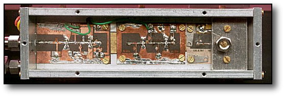
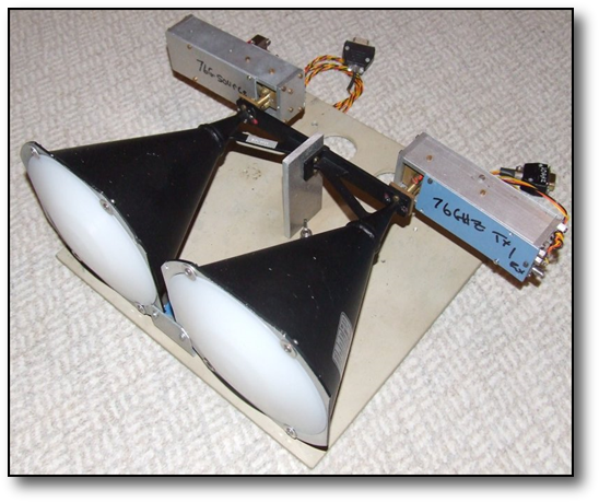
The system shown on the left comprised 2 head units, one receive and one transmit on the rear of two 36dBi 55GHz horns. The receive transverter unit is fed by a PLL local oscillator / multiplier with internal 5Mhz reference and housed in a diecast box described below. This unit can also be used to transmit a low level signal perhaps in the order of 50uW. The other head unit comprised a high power diode multiplier, described below, for FM & CW modes, fed by a free running oscillator and multilpier (not shown here). An FT290 acted as the 145Mhz IF.
This picture on the right shows an earlier 35cms cast dish with penny feed working to G3FYX at his home QTH near Bristol from Tog Hill.
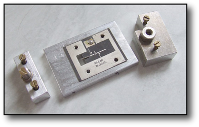
This photo left and below shows the head unit of the 76Ghz DB6NT transverter with, from left to right, the 9.5 to 19Ghz doubler, the 19 to 38Ghz doubler and finally the mixer / doubler pcb using a dual flip chip diode type MAE1318. This unit was mainly used for receive only as its power output on transmit was limited to uW's.
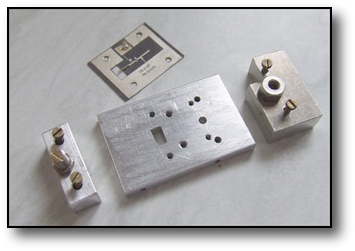
A newer unit shown above dispenses with the 9.5 to 19Ghz doubler and used a Millicom multiplier to go straight from 9.5Ghz to 38Ghz.
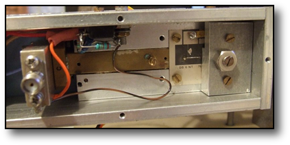


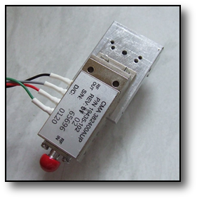
The PLL shown left used the G8ACE Reverse DDS system locked to an on board TCXO 5Mhz source. The small shiny box is the TCXO 5MHz standard and the ReverseDDS is in the larger tin plate box. Also in shot is a low drop out voltage regulator to ensure that operation is satisfactory on low battery voltage. The RDDS was easy to use as it employs a PIC to set an AD9851 DDS chip to the correct synthesis frequency to allow the OCXO to be synthesised down to 5Mhz for comparison with the reference frequency.
On the underside of this box was another containing the G4DDK 004 oscillator/multiplier and a WDG 003 multiplier pcb. The oscillator is nothing exotic and uses the standard DDK004 oscillator with a clip on heater on the crystal and FM applied to allow PLL operation. A G8ACE OCXO would have no doubt been better but was not available at the time the system was developed. There was a temptation to upgrade but as the current system worked, the saying "if it ain't broke don't mend it" comes to mind!!!!
Like the 24Ghz system described elsewhere high stability and good phase noise are a must. Thus the crystal used in the LO must be of high quality and age predictably. The crystals are usually specified for operation with an oven temperature of 60degC and were supplied by Eisch-Kafka.
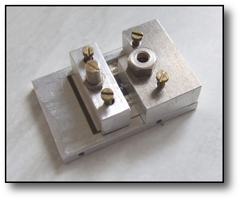
This 76Ghz X2 diode multiplier shown here used a single flip chip GaAs varactor diode type MA46H146 in a DB6NT transverter type pcb, pumped with a 38Ghz Millicom module working as a x3 multiplier. The Milliwave module is driven at ~20-30mW by a 12.66GHz crystal controlled source which can be keyed or FM modulated. Power output at 76GHz has been measured as being ~2.5mW.
Components for the systems shown were available from DL2AM .
Components for the systems shown were available from DL2AM .

The crystal controlled source block diagram is shown on the right and was quickly "cobbled together" from bits I had, to test out the higher power diode source and has now become a fixture!
A DDK004 module was used, but its internal oscillator was disabled and an external ovened crystal oscillator substituted instead. (A G8ACE OCXO and a X24 multiplier might be a better solution but were not available at the time). A X5 multiplier, based loosely on an old WDG 11GHz design using 3, NE325 GaAs fets, follows which then drives the Millicom module.
Listen here to a typical FM QSO on the band over an 18km LoS path
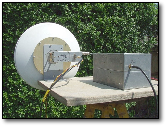
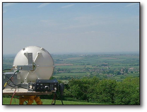
The photo on the left shows testing with a 30cms surplus NuRad dish interfaced with the transverter head unit. Although basically a 38Ghz dish with a WG24 interface, by offseting the 76GHz transverter in the mouth of the feed horn of the dish a reasonable match could be obtained and useful gain realised with this dish, although less than optimum than the horns shown above. This was the overall receive system on the tripod with diecast boxes with PLL REVDDS loop system and multiplier stages.
As waveguide switches are rare at these frequencies, a second antenna was needed on Tx.
As waveguide switches are rare at these frequencies, a second antenna was needed on Tx.
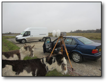
And lastly..............one of the hazards of New Forest operation!
I was active on the 76GHz band for a while and the equipment I used is outlined below. Like my 47GHz kit this equipment has now been sold on, for others to use and enjoy.