122GHz Equipment
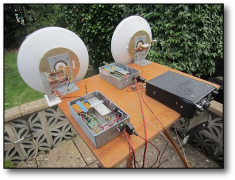
The basic system is shown on the left during garden testing. It comprises two LO's in the diecast boxes and two RF head units coupled to a pair of Nurad 30cm dish antennas fed with horn feeds. The Rx head is on the right and the Tx head on the left.
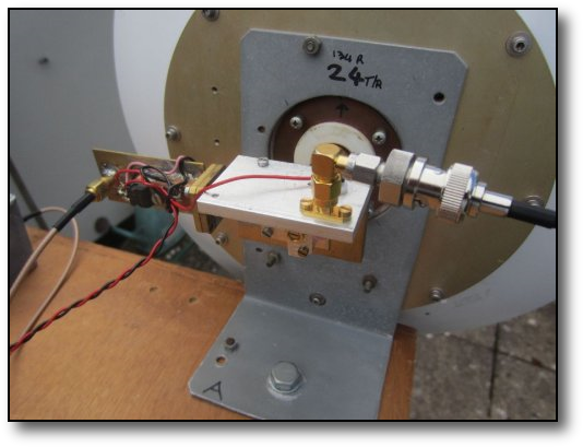
This photo on the left shows the receive side of the system. Its very similar to the transmit side, with a similar LO. The X2 stage and a X5 stage, using an anti-parallel pair of diodes in the receive mixer whose output is coupled to a 144MHz transceiver via a preamp.
The system is almost identical to the 134GHz system described elsewhere. It has seperate Rx & Tx modules and uses a dual dish antenna system shown. Operational mode is CW by keying a X4 multiplier stage.
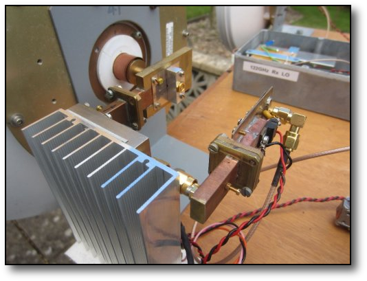
The head unit of the Tx system is shown on the right. It is driven by an LO in one of the diecast boxes shown above and comprises an LMX2541 synth chip running at ~3Ghz. The synth. chip gets its reference from a 10MHz double ovened Morion surplus OCXO.The stabilty of the system working into the receiver shown below is excellent, signals after inital warm up, remaining in the pass-band for many hours. The output from the chip is then applied to a X4 multiplier which produces an output at ~12Ghz. This is then applied to a X2 and a ~150mW 24GHz amplifier bolted to a heatsink The 24GHz signal drives an anti-parallel diode multiplier in the ally box to produce a X5 signal
If you want to see what else is going on in the millimeter field in the UK why not visit these sites too?
http://www.microwavers.org/122ghz.htm
http://www.microwavers.org/134ghz.htm
http://www.microwavers.org/241ghz.htm
http://www.microwavers.org/122ghz.htm
http://www.microwavers.org/134ghz.htm
http://www.microwavers.org/241ghz.htm

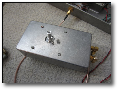
This photo on the right shows the receive side system LO, comprising
the 10MHz reference, LMX synth. module and the X4 GaAs fet multiplier in the tinplate box.
Click here for a quick look at a garden test of the kit in lash up state. Firstly, a source is placed about 9meters. At the camera end where the receiver is, the rx is optimised for best received signal. Note the stabilty of the signal due to OCXO's being used all round. The second part of the video shows the rx and tx co-sited and the signal being "bounced" off the trees some distance away with attendant flutter and fading of the signal.
The 122GHz VK Project
In late 2019, Tim VK3CV announced a 122GHz project that he and others had been working on using a radar chip which covered the band. A lot of interest was shown in this so a kit of parts was made available to other amateurs where you could
1) do it all from scratch starting with a bare pcb or
2) buy a fully populated and working pcb which one only had to box up. Two small horn antennas/ feeds were also made available too.
The chip has 122GHz LO's on board derived from an on-chip ~1.9GHz synthesiser locked to 10MHz reference followed by a X64 mulitplier. The process is not linear therefore it will only support FM or CW. It also includes an LNA.
To see how it compared with my own kit described above I opted for option 2.
Below you can see the results of my lab

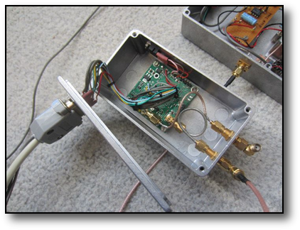

On the left is the pcb in its housing ready to be closed up and mounted on the antenna. A multicore cable connects this unit to a second box just visible housing the control switches and the 10MHz external OCXO which I opted to use instead of the internal TCXO on the pcb. Coax connectors are shown for the external ref. input and the IF output.
The frontside of the unit with the tiny Chapperal feed trial fitted
The same unit with the feed horn fitted for interfacing to the 30cms Nurad dish shown below.
All units fitted and under range test in the garden to a test source about 9m away.
If you want to find out more about the project and progress then visit The122GProject user group.