134GHz Equipment
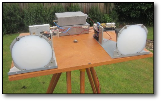
The basic system is shown on the left. It comprises two LO's in the diecast boxes and two RF head units coupled to a pair of Flann 50GHz lens type horn antennas. The Tx head is on the right and the Rx head on the left.
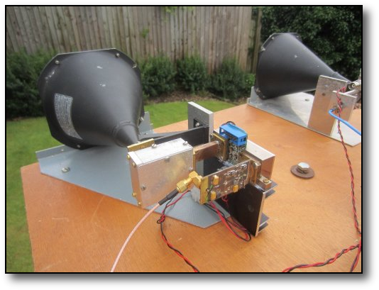
This photo on the left shows the receive side of the system. Its very similar to the transmit side, with a similar LO. The X6 uses an anti-parallel pair of diodes in the receive mixer whose output is coupled to a 144MHz transceiver via a preamp.
The system has seperate Rx & Tx modules and uses a dual horn antenna system shown and is the result of many many hours of blood sweat and hair tearing!!! Operational mode is CW by keying a X4 multiplier stage.
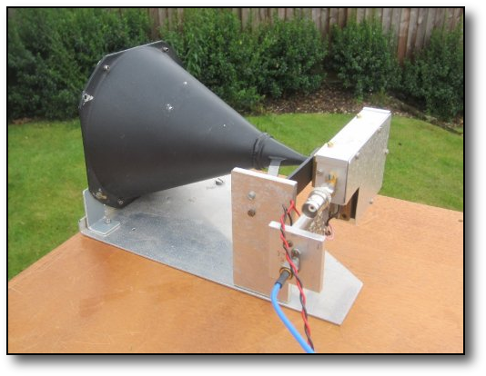
The head unit of the Tx system is shown on the right. It is driven by an LO in one of the diecast boxes shown above and comprises an LMX2541 synth chip running at ~2.8Ghz. The synth. chip gets its reference from a 10MHz double ovened Morion surplus OCXO.The stabilty of the system working into the receiver shown below is excellent, signals after inital warm up, remaining in the pass-band for many hours. The output from the chip is then applied to a X4 multiplier which produces an output at ~11.2Ghz. This is then applied to a X2 and a ~150mW 23GHz amplifier shown right The 22.4GHz signal drives the dual series diode multiplier in the ally box to produce a X6 signal.
If you want to see what else is going on in the millimeter field in the UK why not visit these sites too?
http://www.microwavers.org/122ghz.htm
http://www.microwavers.org/134ghz.htm
http://www.microwavers.org/241ghz.htm
http://www.microwavers.org/122ghz.htm
http://www.microwavers.org/134ghz.htm
http://www.microwavers.org/241ghz.htm
Watch here a recent test with G8ACE at his home QTH over a distance of ~3.5km. Note how stable the signal tone is due to the use of PLL's locked to OCXO's at each end. The equipments had never worked together before, but we found one another within a few khz of the expected frequency of 134.800GHz