Oscar 40
To operate through the nominally geostationary satellite Oscar 40, the following equipment was used.
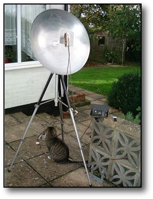
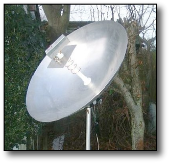
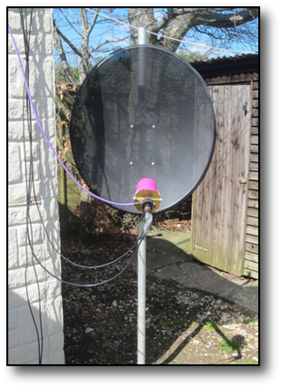
For the L band uplink a 1.1m mesh dish was used, shown above equipped in its "earlier life" with a Meteosat feed, but for Oscar 40 operation a helix feed was used. A 3 band feed was also constructed, but Oscar 40 ceased operation before this could be tried. However preliminary tests indicated that using this dish for reception too produced an excellent downlink signal, althought there may be transmit-to-receive isolation issues to address.
RF power was produce by a homebrewed 1269MHz converter driven by a 145MHz IF. This produced an output of 1W pep on SSB, which was then used to drive a single cavity 2C39A PA to 50-60W output. A very respectable signal was produced using this set up, and while the satellite was at apogee the dish only needed the occasional manual "nudge" to ensure the signal level was maintained, thus no automatic tracking was used.
The dish was made from a kit, long ago supplied by LMW Electronics and comprised the shaped aluminium ribs, welded hub and wire rim. The only extra parts the builder had to supply was some suitable wire mesh, the feed tripod and aluminium solder.
Unfortunately Oscar 40 suffered battery failure some years ago and thus operation ceased.
A 60cms G3RUH dish with a helix feed, and a G4DDK homebrewed downconverter were used here to receive the 2401.3Mhz downlink signals. The latter was located adjacent to the feed to minimise the impact on the noise figure and had a 144Mhz IF. Good signals were heard on this set-up, although with the increasing use of 2400MHz for WiFi some interference was experienced on some dish headings.

Es'Hail 2 (Oscar 100)
This is the first commercial geostationary satellite to carry ham radio transponders. The uplink is on 2.4GHz circular pol. and the downlink on 10.49GHz linear pol. There is a narrowband transponder on vertical pol. and a wideband transponder on horizontal. The latter is for digital TV and the former for speech and data. To date I have only been actively transmitting on the narrowband transponder with SSB since 12/2/2019 when the transponder was released for general use. More information here.
A flavour of the downlink can be heard here
Access equipment is very straightforward and mainly homebrew and comprises a 2.4GHz upconverter from 144MHz from a pcb supplied by W1GHZ. This outputs a signal level of ~20mW to drive a surplus Spectrian amplifier to a level of 25W, but which is now well backed off, to ensure that on speech peaks the uplink SSB signal is never any louder than the satellite telemetry beacon at the band centre.
The receive side comprises a commercial off the shelf SATV Gold media PLL type LNB. The 25MHz crystal is removed and the PLL driven from a DDS AD9852 module which generates a very stable 25MHz signal from an OCXO. The LNB output is at 739MHz which is further downconverted to 144MHz in a simple mixer, IR filter and LO.
All LO's are generated by LTC6946 or LMX2541 synthesisers locked to surplus 13MHz OCXO's.
More on synths and pcbs available can be found here
The converter and amplifier equipment is all located in the garage adjacent to the antennas and linked back to the radio shack in the house, about 10 meters distant, via coax cables at 144MHz.
In the shack I use a Yaesu FT290R on the transmit side tuning around 144.2MHz and to listen to the downlink I use a Kenwood TR751E tuning around 145.2MHz
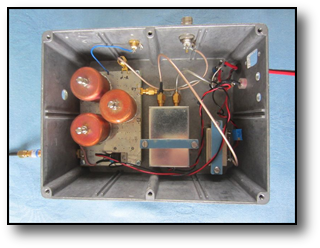
The picture on the left shows the 2.4GHz upconverter with the converter pcb and its pipe
stop filters in place, with next to that the LO synth in its tin box, alongside the 13MHz OCXO. All in a recycled diecast box. Not pretty but it does the job!
stop filters in place, with next to that the LO synth in its tin box, alongside the 13MHz OCXO. All in a recycled diecast box. Not pretty but it does the job!

This is the Spectrian 30W SSPA off eBay.This time in a brand new diecast box. I would have gone for something smaller as the bird is too good and only needs 10W for an "S9" signal. A pleasant surprise for a change.
....and with ~150watts of heat to get rid of
a good heatsink is mandatory
a good heatsink is mandatory

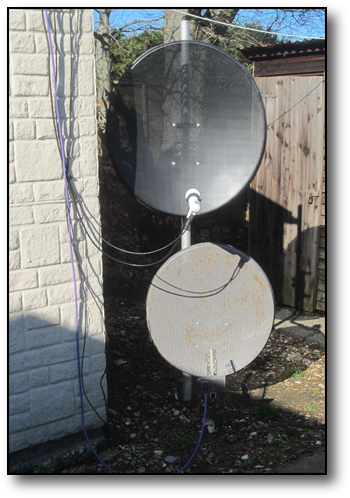
Initially antennas were an 80cm for the LNB and a 60cm for Tx with a helix feed, probably over illuminating it but good enough for starters.
After a months operating experience I decided to make up the popular dual band patch feed from details here.
I obtained some 2mm brass sheet which was then cut to the correct sizes. The next challenge was to make the 22mm holes. Of course my hole punch set only had a 20mm sized punch, so the remaining 2mm was trimmed off very carefully with a half round file. I wanted to get a good clean solder joint between the 22mm pipe and the two plates so opted to use my hot air gun on its maximum setting. After clamping the two plates and the pipe in a vice I used some solder paste round each joint and then turned the heat gun on the whole assembly until the paste melted and flowed freely into the joints. This produced excellent clean joints with minimal cleaning off of excess solder. I'd recommend this technique to anyone embarking on feed constuction.
The LNB feed horn was trimmed off and integrated with the new feed. Of course as sods law would have it the diameter of the LNB "waveguide" was less than the inside diameter of the feed 22mm pipe and it was a loose fit in the pipe. A 22m pipe coupler was bought and some saw cuts made in one end so that the coupler could be compressed down to the diameter of the LNB using a "jubilee" clip of the type used to anchor rubber hoses to metal pipes. The whole lot was then waterproofed with PVC tape. Quite ugly but it seems to work okay! An empty stain remover container was pressed into service as a make-shift radome. The results are shown in the photos here. Pleased to say the new dual band feed with single dish arrangement works very we


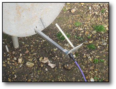
Feed with and without radome fitted
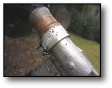
LNB to feed interface
Having successfully operated through the NB transponder I decided to have a look at the WB transponder and the DATV operators on there. The "modded" LNB didn't seem to operate well on there as the phase noise off the external refrence was too great. I thus fitted a very cheap single output Goldstar LNB made for normal DTV reception and kept it unmodified. Stable enough for DATV but not SSB.
The DVB2 DATV low symbol rate cannot be received by normal DTV receivers / decoders so I built the miniTouner from a kit of parts sold by the BATC to members and specially designed for "narrowbandwith" amateur DATV.
The software allows recording of received signals and the results can be seen in this sample which I put on YouTube.
No current plans to transmit DATV however.