Spark
Gap Transmitter Signals for Marconi Centennial
12 December 1901 to 12 December 2001
 Spark gap transmitter signals in today's
radio spectrum could be considered analogous to horse and buggies
on our motorways, but during commute rush hour they may actually
out perform rival cars with their impatient drivers. There are
legal equivalents as well. However, exceptions for the banned
Spark Gap Transmitter apparently are being made for the Marconi
Centennial where under controlled conditions they may be used.
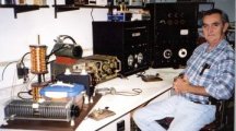
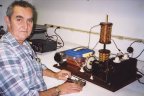
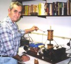
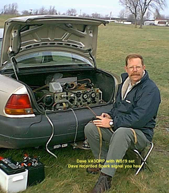
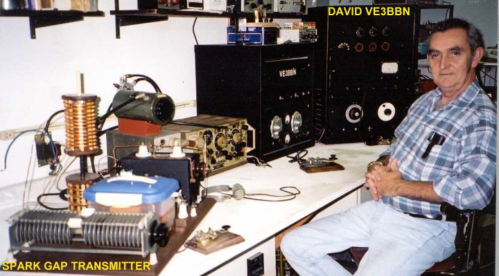
One such transmitter has been constructed, tested by David Wilson
VE3BBN and given the green light in Canada. The background sound
is a test signal heard and recorded by Dave VA3ORB 150 miles away
on
Spark gap transmitter signals in today's
radio spectrum could be considered analogous to horse and buggies
on our motorways, but during commute rush hour they may actually
out perform rival cars with their impatient drivers. There are
legal equivalents as well. However, exceptions for the banned
Spark Gap Transmitter apparently are being made for the Marconi
Centennial where under controlled conditions they may be used.
One such transmitter has been constructed, tested by David Wilson
VE3BBN and given the green light in Canada. The background sound
is a test signal heard and recorded by Dave VA3ORB 150 miles away
on
3 November 2001. Click here for more picture
detail.
If
you are over 90 years of age you may have heard spark gap
transmitter signals long ago. If not, have a good listen as you
probably won't get another chance to hear such signals for
another 100 years!
The
following Ontares Net members in Canada reported hearing this
signal:
VE3UCI
Brian
Kilworthy
110 miles
VA3JNA Joe
Owensound
130 miles
VA3BBD Percy
Owensound
" "
VE3SUT Dave
Elliot Lake
270 miles
VE3BDB Bob
Orillia
100 miles
VE3OF Harry
Fenelon Falls
100 miles
VE3MIO Maureen Manitoulin Island
250 miles
VE3EAV Hugh
Echo Bay
450
VE3LJG Lloyd
Saulte Ste Marie
450 miles
VA3ORP Dave
Kingston
150 miles
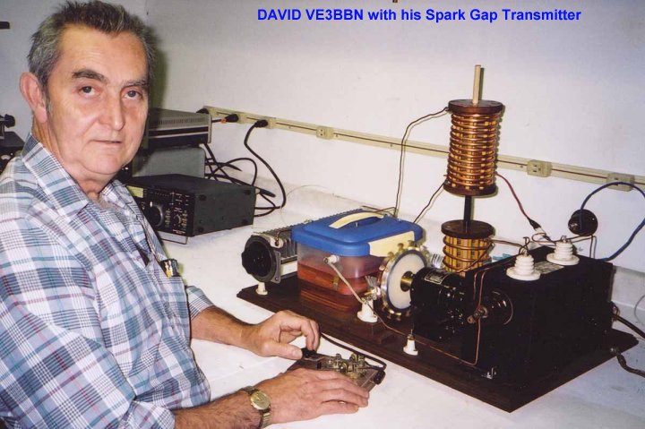
Marconi
Day Schedule for Spark Gap Transmissions by David VE3BBN
This is the
official notice for the spark event: Transmissions will be
between 2100 and 2200 hours local Canadian Eastern time.on 12
December 2001 (between 0200 and 0300 Zulu on 13 December 2001)
Note that Europe will already be into the next day 13 December
2001.
The freq. is 3.550
mhz bandwidth approx. 20 khz power out approx. 15watts.
Transmission will begin on the hour for approx. 15 seconds and
rest for
45 seconds to begin on the next minute mark.
The message will be "MARCONI S"
repeated each minute for the hour.
Receivers should be operated in the AM mode for best bandwidth.
and
detection.
If the signal is heard please QSL to [email protected] with the following :
Your call, rst, distance from Niagara falls Ontario as the crow
flies.
Click here
for initial Marconi Centennial Transmitting results:
SPARK
GAP TRANSMITTER DETAILS
 A
schematic of the spark gap transmitter is shown on the right.
Keying is accomplished by switching the ac voltage to the primary
of the power transformer on and off with relay contacts. The
secondary output voltage of 12kV powers the transmitter by
charging up C1. The rotary spark gap discharges C1 into the
primary coil of the RF transformer. During this discharge when
the spark gap is firing, the capacitor and primary coil oscillate
at their natural frequency (approximately 3.56MHz. This burst of
oscillation is loosely coupled into the high Q secondary circuit
which is also tuned to 3.56MHz. Output RF is taken from a tap one
turn off the bottom of the secondary coil and fed to a Windom
antenna.
A
schematic of the spark gap transmitter is shown on the right.
Keying is accomplished by switching the ac voltage to the primary
of the power transformer on and off with relay contacts. The
secondary output voltage of 12kV powers the transmitter by
charging up C1. The rotary spark gap discharges C1 into the
primary coil of the RF transformer. During this discharge when
the spark gap is firing, the capacitor and primary coil oscillate
at their natural frequency (approximately 3.56MHz. This burst of
oscillation is loosely coupled into the high Q secondary circuit
which is also tuned to 3.56MHz. Output RF is taken from a tap one
turn off the bottom of the secondary coil and fed to a Windom
antenna.
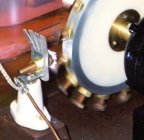
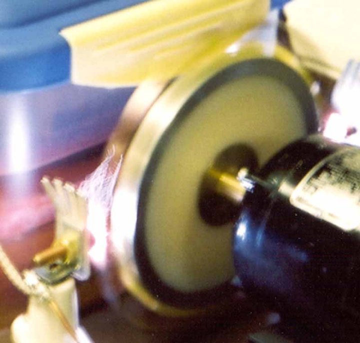
The rotary gap
can fire on both positive and negative polarities of the 12kV
applied voltage. The ratary gap fires at a minimum of 120 times a
second giving a minimum of 120 bursts of RF a second. Actually it
is firing at about 6 to 8 time each 60Hz cycle or about 360 to
480 times a second. As such the transmitter output consists of
about 360 to 480 bursts of 3.56MHz averaging about 15 Watts.
C1 is a home
brew sandwich type constructed capacitor immersed in high grade
transformer oil. This arrangement provides a highly stable
capacitor. Pressure is applied to the top of the capacitor with a
turn screw for fine tuning the primary circuit.
Protection
against high voltage spikes (in excess of 18kV) is provided by
the safety gap. The rotary gap consists of 16 rotating electrodes
against 2 stationary electrodes. The spark gap acts as a voltage
controlled switch: open when not firing, and short (~2 ohms) when
firing. The power transformer is a Neon Sign transformer rated at
12kV 60mA. The coefficient of coupling is approximate 0.95. Thus,
when the secondary winding is short circuited by the rotary spark
gap, the maximum currwnt is limited to 60mA.
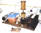
More pictures:
Click on images to enlarge. (back space to return to this page)


HOME PAGE


