CROSSED DIPOLE ANTENNA FOR SATELLITE RECEPTION
![]()
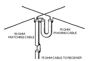
a simple antenna for receiving satellite images from the 137 MHz band is the crossed dipole or turnstile antenna, it can be constructed at home without too many problems (bear in mind this antenna is for 137 MHz, if you want to make one to monitor the packet transmissions from the international space station on 145.800 MHz, you will have to scale it accordingly, the driven elements now become about 48.5 cm, instead of 51.5 cm.the phasing ( 50 ohm cable ) could be left out if the antenna is just for receiving, or the cable length to the tcvr is short .
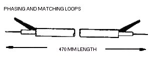
1) Make the matching loop out of 50 ohm co-ax and the phasing loop out of 75 ohm co-ax - see fig 3 for details.
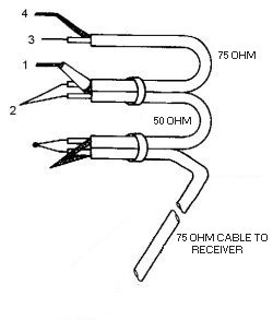
2) Arrange the two loops and the 75 ohm cable to connect to your receiver as shown in fig4 - connect together using plastic tie clips.
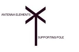
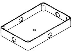
3) Drill four holes in a plastic box- the box can be about 4" x 3" - to take the 4 antenna elements. I used 13 mm dia aluminium tubing. Make sure that the elements sit flush with the bottom or inside of the box. Also drill a hole in the top centre of the box to take the screw to hold the box to the supporting pole - a 3/4" or 1" piece of dowel about 3 - 4 feet long will do as the support. See fig5 / fig 2 for details.
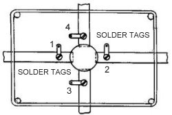
4) drill a hole about 3/4" from the end of each antenna element to take a self tapping screw to hold the solder lug - put the 4 antenna elements through the holes in the plastic box, the ends resting up against the supporting pole. Now araldite the aluminium tubes into place (any other epoxy glue will also do) be quite liberal with the araldite - but don't get it onto the solder lugs. See fig6
5) Now solder the cables fig4 to the relevant solder lugs on the elements fig6.tape the loops and the connecting cable to the supporting pole. Seal the ends of the co-ax cable with more araldite. Put a suitable connector on the end of the lead to your receiver - mount the antenna on a mast outside or even in the house loft space.
|
FIG1
|
FIG2
|
|
FIG3
|
FIG4
|
|
FIG5
|
FIG6
|

![]()