Brian Smith G0IER

48 , Colchester Close ,
Toothill,
SWINDON
Wiltshire
SN5 8AG

THE ' MIGHTY - WIDE ' SIX METRE DIPOLE

This article describes a simple but effective wide bandwidth six metre antenna. Construction
details are for an indoor version , sturdier materials and weather-proofing could be added for outside use.

Simple , easy to build , and excellent standing wave ratio across the whole of the six metre amateur band.

Every single loft mounted six metre antenna that I tried had one frustrating problem. Lack of bandwidth. The best performance I could get was a usable bandwidth of about one megahertz.
using the ' double coaxial ' dipole arrangement featured in my ancient copy of Pat Hawker's G3VA book " Amateur Radio Techniques ".

This is only half the bandspace available to United Kingdom amateurs , and left me with a choice of the morse section of the band OR the frequency modulated ( F.M. ) portion. Not both .

Not wanting to be restricted to one portion of the band only I continued searching for a suitable wideband antenna.

An intriguing design was eventually found in the Amateur Radio Relay League Antenna Handbook. ( Chapter 15 - 1 )

I rescaled the antenna for use on the        six metre band and also modified the tuning arrangement. The results were excellent so I have detailed them in this article. Anyone who wants to try six metres
will find this a superb utility antenna.

The antenna offers the benefit of folded dipole construction , which is a wider bandwith , plus the convenience of fifty ohm coaxial cable feed. Other positive points of the antenna are:

1 - Simple 50 ohm coaxial feed design

2 - No Antenna Tuning Unit required

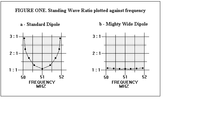
3 - Wide Bandwidth - 50 . 00 to 52 . 00 Megahertz

4 - Lightweight - ideal for portable / indoor use


The difference between the " mighty - wide "six metre dipole and its nearest rival makes an interesting comparison. I have plotted the Standing Wave Ratio of the antenna and the coax dipole . The results are shown in

FIGURE ONE.
                    Construction of the dipole is simple. My antenna is loft mounted so the constructional details given here can be considered for an indoor or portable version of the antenna.

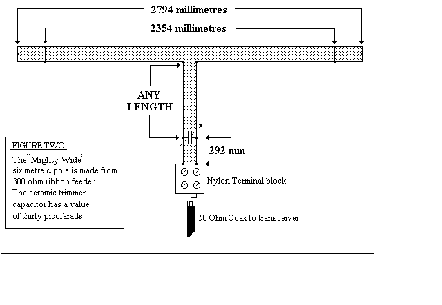
The whole dipole is made from ribbon cable of the three hundred ohm type . Details of the device
are shown in FIGURE TWO.

I used the non - slotted variety of ribbon cable , which is available from the Maplin catalogue. The radiating element of the antenna has a total length of 2794 millimetres. The antenna feedpoint is connected to a section of the same ribbon feeder. This section can be of any length ,which is most convenient for siting the antenna.
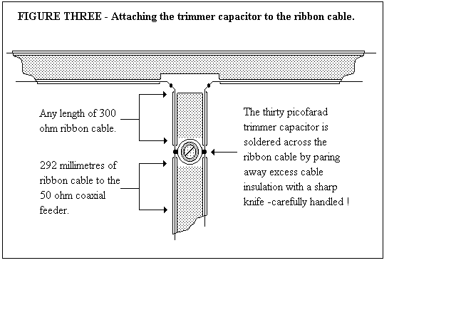
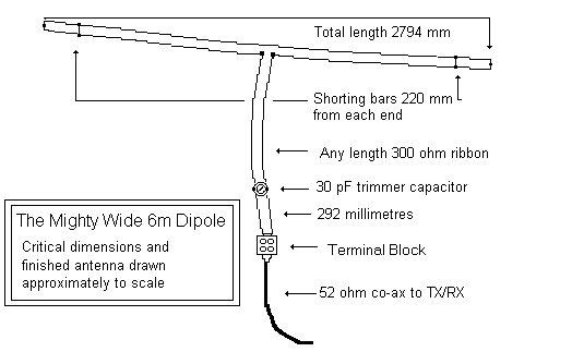
Two shorting links are placed across        the ribbon cable radiating element. The links are placed at distance of 220 millimetres from each end of the antenna. I soldered the shorting link wires across the ribbon cable by first paring away excess cable sheathing with a sharp modelling knife. Do be careful if you try the same technique, or you may need to add elastoplast to the component list !

A thirty picofarad ceramic trimmer capacitor will be required. The trimmer is used as a capacitive reactance element. This transforms the antenna impedance down to fifty ohms.

I had one in the junk box , but this item should still be available from the Cirkit
electronics constructors catalogue. The trimmer capacitor is soldered across the ribbon cable as shown in FIGURE THREE.                
I used the same paring technique detailed earlier to expose the ribbon cable conductor. Remember to
leave a length of ribbon cable below the trimmer capacitor. The fifty ohm coaxial cable from the transceiver is attached to the ribbon cable at a point 292 millimetres below the trimmer capacitor connection point. Electricans terminal block makes an ideal connector for attaching the coax cable to the ribbon cable.

After building the " mighty wide " dipole I mounted the device in the loft. I adjusted the trimmer capacitor for the best standing wave ratio with the transceiver tuned to a frequency of 51 . 00
Megahertz. I was delighted to find that after adjustment the S.W.R. ratio hardly varied across the
whole of the United Kingdom six metre band allocation of 50 . 00 to 52 . 00 Mhz.             I tried the antenna in several positions . This included using an inverted V mounting. The trimmer capacitor did not need to be re - adjusted for any of the positions tried. All in all I have found it to be an extremely useful antenna . I can now cover the whole six metre band with no antenna tuning unit
required . I am now considering rescaling the device for use on the W A R C bands of
12 and 17 metres. I may even put one up for use on ten metres when things improve !
73 de Bri G0IER

Back to Antenna Index

Back to Home Page