Transmitter Harmonic Filters
1. Low Pass Filters for 70 and 144MHz
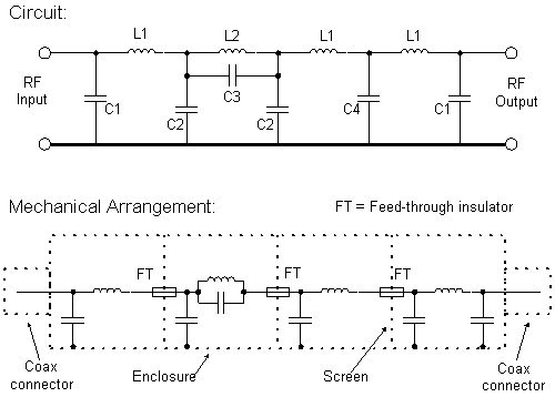
The following 50ohm impedance filters are straight-
The design uses a four section constant-
The tables below show the values and measured performance for each band. Values may be scaled for other bands of interest.
|
Values: |
|
|
|
|
|
|
|
Band |
C1 pF |
C2 pF |
C3 pF |
C4 pF |
L1 |
L2 |
|
70MHz |
40 |
64 |
20 |
80 |
5t 0.375inch ID |
3.5t 0.375inch ID |
|
144MHz |
20 |
32 |
10 |
40 |
4t 0.25inch ID |
3t 0.25inch ID |
All inductors are wound with 18swg tinned copper wire with turns spaced approximately one half the wire diameter. ID = Inner Diameter.
Attenuation Results:
|
Band |
<0.2dB |
- |
- |
- |
- |
|
70MHz |
75 |
80 |
100 |
103.5 |
To 500MHz min |
|
144MHz |
150 |
160 |
192 |
205 |
To 500MHz min |
All frequencies in MHz
The notch figures are typical of a production run and are determined by the adjustment of L2.
Each filter should be adjusted for minimum passband ripple and minimum loss at the frequency of interest by small variations of the turns spacing of each inductor. L2 may be adjusted to obtain the -
Conventional 500v disk ceramic capacitors but not miniature or plate types should be good for at least 50 watts transmitter power output. Concentric feed-