Switch Wafer Repairs / Rebuilds
1. Repairs
Paxolin or SRBP switch wafers are easy to break due to their thin construction, age or problems in their disassembly. One possible method of their repair is presented here and has been used by the author many times with success. It uses a flat wooden jig to hold the wafer in place and an elastic band around the circumference of the wafer to provide some pressure to gently hold the surfaces together while the epoxy resin adhesive cures. Crucial to the ultimate success is degreasing the wafer so that the adhesive can bond with the wafer material.
I use a piece of clean flat wood about six inches (150mm) square in which two pieces of short threaded rod or the equivalent bolts are fixed with the threaded sections protruding upwards from the top surface. The length, diameter and spacing will depend on the wafer being repaired but 6BA (3mm diameter) seems to work for most. The threaded sections are spaced apart so that the wafer will fit onto them using its own switch mounting holes without catching and they are held in place with washers and nuts on the top side. Do not counter sink the nuts on the top surface as they will keep the wafer away from the wood surface.
Find a thick elastic band that will just fit around the outside circumference of the wafer and tight enough to apply some pressure to the wafer.
Degrease the wafer and dry thoroughly.
Mix up some epoxy resin adhesive (Araldite or similar) and apply sparingly to the surfaces to be fixed together -
Mount the wafer onto the threads on the jig with washers each side and hold in place with nuts that are only finger tight. Make sure that the glue joint is not disturbed by this process.
Leave to set at room temperature for at least 24 hours. You can accelerate the setting time by leaving the jig in a warm location like an airing cupboard. When warm, most mixed epoxy adhesives will acquire a thinner consistency before they set.
NOTES
a) If the glue joint comes anywhere near the threaded fixings on the jig or the jig surface, use a piece of cling film or a polythene washer to keep the adhesive away from the surface or the threads -
b) This repair process assumes that the wafer is only in two pieces and that you have the rotatable centre section and all broken pieces. If additional breakages have occurred then you may have to assemble the individual pieces one at a time using different fixing jig methods until the wafer will fit on the jig for its final repair. I have used this method to fix wafers that have ended up in several pieces.
c) Keep the de-
d) Excess adhesive can be filed, scraped or cut away as required once setting has commenced or completed.
3. Wafer Rebuilds
As part of my SB-
The task was now to remove the switch contacts from one set of wafers and fix them to the other set of wafers so that I had a set of single pole nine way wafers with the shorting facility in place. The following photo shows the original wafer front and rear on the left and the final wafer front and rear on the right.
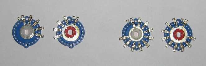
Removing the switch contacts is not too difficult as the retaining rivets may be drilled out carefully with a sharp drill, making sure that the contacts are not damaged in the process. If the rivets rotate during drilling then solder a piece of 18SWG wire to the rear side of the rivet and hold that in a vice -
I was unable to obtain small quantities of replacement rivets so I used 10BA x 1/4inch brass nuts and cheese head bolts which are a good fit but a little difficult to manipulate -

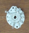
The magnified photo to the right shows a completed wafer with the five extra switch positions and retaining bolts just visible on the lower part of the wafer. The 10BA nuts were varnished to hold them in position and the front and rear contacts can be joined with a wire so that electrical contact does not rely on the nuts and bolts.
A miniature screwdriver and 10BA box spanner helped considerably.
The band switching arrangements in the new SB-
4. Increasing Switch Current Capacity
If a particular switch lacks current carrying capacity then you can connect two adjacent identical wafers in parallel but this requires considerable extra space. A better solution is to add additional fixed contacts to the other side of a single wafer plus a new rotating contact and connect these to the contacts on the first side. This option is not always possible and depends on the structure of the wafer so some inspection is required.
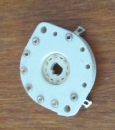
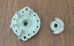
The first wafer front and rear views shown on the upper right two photos cannot easily be modified as the rear side of the wafer lacks the moulded supports for the contacts. This switch has been cleaned in a silver dip.
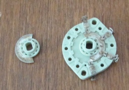
The second switch front and rear views in the lower two photos does have the required supports and is relatively easy to modify. One of the centre sliding contacts is shown separately. If you do not have any suitable replacement rivets then 8BA nuts and bolts are suitable for fixing the contacts but do use a ripple washer and avoid over-
When cutting the centre contact to size, use a miniature hacksaw, light cutting pressure and finish off all cut surfaces with a fine rat tail file. Do not use tin snips or side cutters for cutting as they distort the moving contact material. If required the metal contact may be removed from the ceramic carrier, held in a vice for for cutting and finishing and then replaced in the carrier.
Most switches of this type require a retainer to keep the sliding contact in place so you will need an additional one of these plus any positioning spacers on the threaded support sections. Some of these switch types also have a small spring under the rotating contact -
2. Switch Cleaning
a) Switch cleaners like Electrolube are ideal for cleaning contacts but SRBP wafers do absorb the cleaning fluid, attract dust and it is difficult to remove it. It is best to apply the cleaning fluid directly but sparingly to the metal contacts with a cotton wool bud.
b) Heavily tarnished silver plated contacts can be significantly improved by disassembling the switch and putting each wafer in a silver dip for a few seconds. When the tarnish has been removed, thoroughly rinse each wafer in clean water, dry and leave in a warm place like an airing cupboard for a day or two to remove any absorbed moisture. The switch may then be re-