SB-
1. Adding coverage for Top Band (1.8-
This is an overview of the steps required. Rather than lose an existing band position I elected to add an extra position to the band switch which requires some major surgery so this is not a task for the faint-
To provide full band coverage for 1.8-
An additional inductor is required in the PA compartment to resonate the PA tank circuit on 1.8MHz and additional loading and tuning capacitors are required under the chassis to match to 50ohms.
You will need to remove all of the printed circuit band boards attached to the band switch and remove all of the switch wafers from those PCBs so a solder sucker and fine desoldering braid are essential.
Adding extra positions to each wafer requires access to either a switch kit or unused switch wafers from which spare contacts can be removed -
Most of the switch wafers carry out more than one function and in some cases the shorting mechanism must be removed and one position cut back to ensure that the switch behaves correctly in the 1.8MHz position -
The modification works very well and is well worth the effort but you need lots of patience and a clear understanding of each switch wafer function. I sketched each required change before starting work.
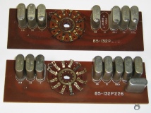
The first two photos show the crystal oscillator PCB before and after the extra band crystal has been added. Note the need to cut and join the tracks to accommodate the extra crystal.
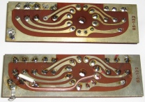
The photo below and the two to the right show the band oscillator anode tuned circuit PCB with the extra tuned circuit in place. The base of the former is anchored to a splined PCB pin that has been inserted into the PCB.
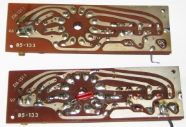
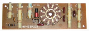
The two photos to the right show the driver plate PCB before and after with the extra band tuning capacitor in place. The 3.5Mhz tuned circuit has been rewound with additional turns in order to increase its L-

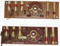
The two photos to the right show the driver grid PCB before and after with the extra band tuning capacitor in place. The 3.5Mhz tuned circuit has been rewound with additional turns in order to increase its L-
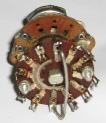
The photo to the right shows the PA switch after modification for the extra band position, removal of one section of the shorting wiper and an extra wafer to switch in an additional 300pF high voltage tuning capacitor for 1.8Mhz.
This photo shows the refitted PA switch with the additional tuning and loading capacitors for 1.8Mhz. The white capacitor is a high voltage 300pF tubular ceramic type.
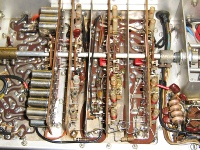
The photo to the right shows the lower RF compartment with the screen removed, all of the modifications completed and the PCBs refitted.
In each case, right click on a photo and save it on your own PC hard drive for future reference.
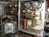
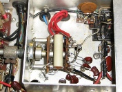
The photo to the right shows the upper PA compartment with the extra Pi tank inductor. The additional loading and tuning capacitors are located in the lower PA compartment shown in photo above this one.
There is no reason in principle why these changes could not be made to an HW-
If you feel that the changes are too difficult or complex then another suggestion is to find another similar Heathkit multiband transceiver and modify it for 160m, the WARC bands and possibly 6m. This can be done without any of the above band switch changes. If you add 6m then do check the spurious responses as the image from the final conversion process is closer as a proportion of the band frequency compared to the 28MHz band -
2. Microphone Amplifier
Whilst measuring DC voltages I discovered that the screen grid voltage of the mic amplifier V1A was higher than the anode voltage which is not recommended. The resistor values were correct and replacing the valve made no difference so I changed the anode resistor to 220K and the screen grid resistor to 1Meg. This resulted in a 6dB increase in audio gain and the voltages being more in line with expectations. No changes were made to the circuitry around the triode section V1B.