RF Switch Box
The recent upgrading of my Yaesu FT-
The switch box is used to ease the problems of selection and sharing aerials and has been designed in the Heathkit style to fit into an SB600 loudspeaker box with the speaker removed and new front and rear panels and chassis constructed.
Front and rear panels after painting and before lettering:
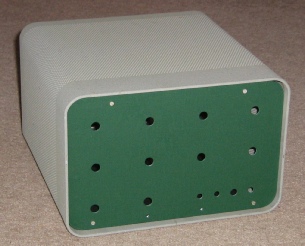
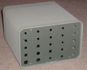
The internal structure consists of a flat chassis tying the lower edges of the front and rear panels together with a pair of aluminium support rods at the top of each panel. The original SB-
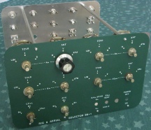
I have now made all ten RF rotary switches and labelled both front and back panels with Letraset and a protective lacquer. Assembly has finally been completed as you can see from the following series of photos:
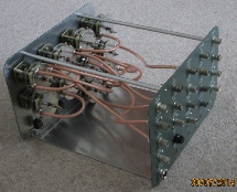
All inter-
Front and rear screening plates are employed around each wafer to get close to a microstrip like environment -
The coaxial cable must not be bent too tightly as the inner insulation will distort so I have used a bend diameter of about two and a half inches. Care is also required when cutting the outer and inner insulation layers to avoid catching the braiding and solid centre conductor -
Minor nicks to the braiding do not usually cause any problems as the solder will wick into the braiding, bypassing any small cuts but there is a more significant risk with nicking the centre conductor which may then fracture if any bending pressure is applied.
The switch for 23cms provides DC to an external coaxial changeover relay.
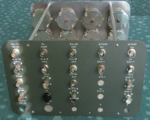
The partially wired unit can be seen to the right.
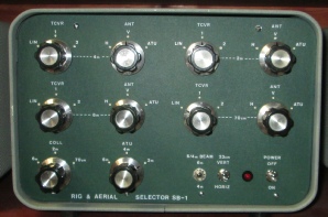
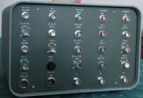
The following pictures show the completed unit front and rear panels.
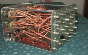
The photo to the right shows the completed internal wiring -
The wiring was completed from the bottom up as getting past cables already in place is not easy.
The DC supply comes from the station console.