Reforming Electrolytic Capacitors
Warning: The voltages involved with most electrolytic capacitors used in valve based equipment are lethal. If in doubt seek expert help. The old adage -
1. Current and Voltage Limited Method
The electrolytic capacitor is a critical part of both old and modern electronic equipment which must be used correctly in order to get the longest and safest operational life and this is particularly important with high voltage versions of these components. Electrolytic capacitors rely on an electro-
The correct course of action is to ensure that each electrolytic capacitor’s insulation layer is ‘reformed’ by the application of a current and voltage limited DC supply to each individual capacitor. Current limiting ensures that the heat generated within the capacitor is kept at a sufficiently low level that damage does not occur. My preferred method is to carefully disconnect each electrolytic capacitor and apply a voltage, equal to the working voltage of the respective capacitor, via a suitable current limiting resistor to that capacitor.
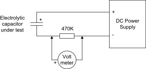
For example, for a 450V working capacitor, I apply 450V DC, observing the correct polarity, via a 150K to 470K 2W resistor to the capacitor and measure the voltage drop across the resistor with a volt meter -
The circuit below assumes that the negative line of the power supply is connected to ground but this is not mandatory. Should the positive line be grounded instead then move the 470K resistor to the positive side of the capacitor. Care is needed if the capacitor case is internally connected to one of the capacitor wiring tags.
Over a period of time, which can be up to 24 or more hours for older components, the voltage across the resistor will fall and eventually stabilise at some much lower value. My rule of thumb for high voltage units is that if the voltage drop across the resistor after 24 hours is significantly more than 22V (indicating a leakage current in excess of 50 microamps) than I repeat the reforming process. If no improvement is obtained then I replace the capacitor with a new one. You may also find that very old capacitors have dried out and cannot be reformed in which case they must be replaced. A similar process may be required for new electrolytic capacitors that were manufactured only one or two years ago -
Capacitors with higher capacitance values will have higher natural leakage currents and may require a correspondingly lower value current limiting resistor. For lower voltage capacitors like 10,000uF 25v I use a 10K series resistor on a 25V DC source.
Once the reforming process is complete, switch off the reforming supply, discharge the capacitor with a resistor (not a short circuit), disconnect it from the reforming supply and reconnect it to its original circuit. As soon as any further inspections or tests on the equipment are completed then it may be powered up.
This method seeks to rebuild the chemically generated insulating layer in a safe manner. However, it does not guarantee that the series resistance of the capacitor is sufficiently low to allow efficient operation. If you have an ESR meter then use it on the capacitor after reforming and discharge is complete -
NB Another well known but separate problem with older equipment is that solid carbon (or carbon composition) resistors will gradually show an increase in their resistance and it is not unusual to see increases from 50% to 500% after periods in excess of twenty years. All resistors outside of their original tolerance should be replaced -
2. Alternative Reforming Method
It has been suggested that a variac and a low power incandescent light bulb wth the same working voltage as the incoming supply connected in series with the AC supply to the unit in question may be used to reform electrolytic capacitors without the need to remove them from circuit. The unit is connected to the variac and bulb and powered up with the variac set to zero. The variac is increased to say 10V or sufficient to make the bulb glow weakly and then left for a few minutes after which the bulb should be glowing less brightly. The process is repeated until the variac is set to output the correct mains voltage for the unit under test.
This may well work but my concern is that the lamp may not provide sufficient current limiting to prevent capacitor damage. One downside of this method is its use where there is a constant current drain by the unit under test -
There is an additional problem in selecting the bulb with the correct power rating for each application.
I do not recommend this method and my preference is for method 1, even though it may be more complicated, take more time and require more patience.
3. Supply of New Electrolytic Capacitors
Modern electrolytic capacitors are much smaller than those manufactured in the 1950s and 1960s so it may be possible to place new capacitors into the emptied cans of older units and there is at least one company in the USA who offer to do this for capacitors used in older well known units like Heathkits.
I always reform new electrolytic capacitors (as their date of manufacture may not be accurately known) and provide inrush current limiting on large power supplies.