Re-
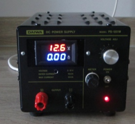
I have owned a Daiwa PS-
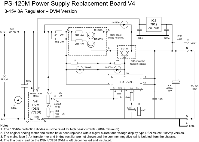
The initial solution was to remove the internal PCB and design a new one that would hold increased smoothing capacitance and use an L200 regulator IC driving a pair of TIP3055 transistors with current sharing resistors mounted on the rear heatsink. Unfortunately I could not make it short circuit proof and the output devices failed twice using both NPN and PNP configurations so I went back to a tried and tested design using a 723 regulator and NPN current amplifier.The original mains transformer, bridge rectifier, and indicator LED were retained. Despite the output device failures the L200 still worked perfectly.
The new circuit is shown below based on information in the 723 data sheet and previous well used designs.
The original smoothing capacitance was increased from 5 x 3300uF to 6 x 4700uF and a new current and voltage DVM (DSN-
The finished power supply provides an output voltage of 3 -
The output fuse will blow if:
- a permanent short circuit occurs on the output and the internal current limit has failed
- An external (high current) reverse polarity potential is applied to the output terminals. The output diode (1N540n) will protect against low to medium current external reverse polarity sources